By Sallye Coyle, February 11th, 2020 An old theatre prop in the form of a tree greets you as you enter the back door of the Set Design Studio at Mendocino College in Ukiah, CA. The back side sports black marker lines for a jigsaw to cut out the leaves and branches, and a metal frame is welded together to provide support. Functional. But Steve Decker, CVPA Technical Director and instructor of Technical Theatre and Design, had plans for how to update the skills that could be taught through the theatre program at Mendocino College. As part of his hiring contract, he requested a ShopBot CNC router with vacuum hold down and a new welding set-up. The funds for purchasing the equipment came in the form of a Workforce Development grant from the State of California. With the purchase made, Sallye Coyle headed to Ukiah in December, while students were on winter break, to install and train people on the use of the new CNC.
The first order of business was to get the ShopBot PRSalpha 5’ x 8’ built and the vacuum hold-down system prepared. The system that they have on their tool uses a Becker Rotary vacuum pump that will pull a vacuum through the top layer of bleeder board (MDF) to hold down a large sheet of material. The Becker is a heavy critter, and so it helped that Steve and Sallye had planned ahead to know where it would sit under the ShopBot table, and what equipment would help get it out of the crate and into position. Steve had a lift jack to move the Becker crate, and a forklift with chains ready to go when the table was partially built and in the approximate final location.
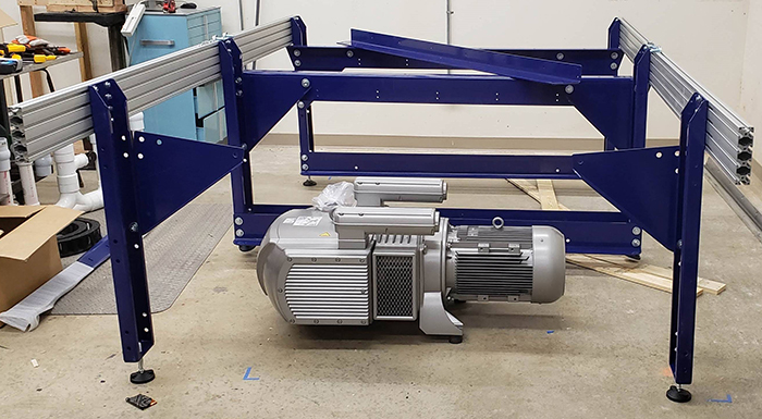 The Becker pump in place under the second “bay” of the ShopBot table. Hot air exhaust will blow away from the operator and avoid heating up the ShopBot Control Box, which will sit at the far right hand side in this photo. The operator will stand at the far left side. Note the ring on the top right side of the Becker pump (one of two) that helps to lift the pump into position.
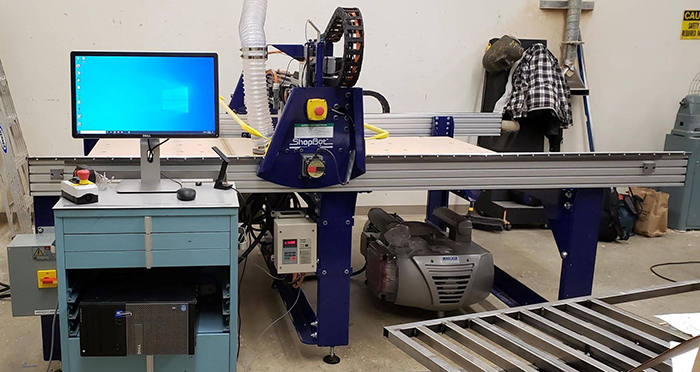 The ShopBot CNC in its final position, with the Becker Pump shut off box mounted on the ShopBot table leg near operator. The VFD for controlling the spindle is also mounted on the side of the table near where the operator will be. The ShopBot Control Box is mounted on the far side of the table, away from the operator. As a reminder, the computer station is positioned at the “Front” of the ShopBot (the long rails are the X-axis), and the spindle moves along the gantry in the Y-axis. The plumbing for the vacuum hold-down system is not yet in place. Vacuum and other kinds of hold-down are worthy of a blog of their own, so this blog will concentrate on the types of files that Steve and Dave, faculty members of the theatre program, worked on during training.
For every training, Sallye likes to demonstrate the three major categories of toolpath options, and the bits that are related to those toolpaths.
MACHINING TO ONE DEPTH: FLAT END MILL BITS
Profile (inside, outside, or on the design line or vector), pocket, and drill toolpaths are toolpaths where the bit plunges to depth, then stays at that depth for the entire operation or pass. Flat end mill bits like the ¼” down spiral, ¼” up spiral, and ¼” and ½” straight bits that are found in the ShopBot starter bit kit are the bits used for those types of toolpaths.
While Steve was familiar with running a CNC machine, and engineering design software such as Fusion 360, his co-worker, Dave, is a painter and artist, and was a bit dubious about the skills needed to design a file, choose a bit and toolpathing option, and cut out a part. So, his “homework” one evening was to draw something on paper, then scan it and save it on a thumb drive. Since a scanned object is a bitmap rather than a vector, we imported the scan into VCarve Pro, and used the trace function to find the edges of the spider he had drawn. With a few other tools in VCarve, we cleaned up the new vectors, then created a profile toolpath to cut out the spider with an end mill bit. Each opportunity to actually cut something out is an opportunity to go through the steps for setting up the ShopBot for machining, so Dave ran through the check list to be sure that everything was ready to start a file: correct bit in place, ShopBot zeroed out in the X and Y axes, z-zeroed using the Z-Zero plate on top of the material, spindle power on, etc.
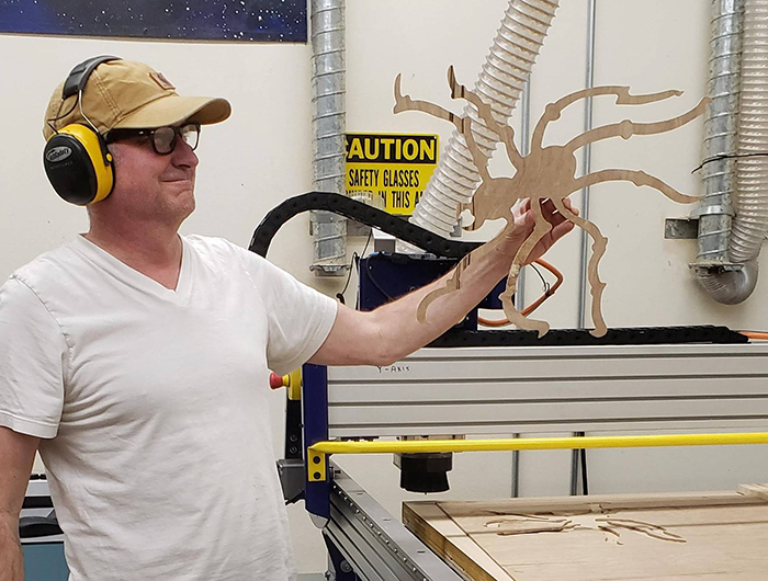 Dave showing off his spider after machining out of ¼” Luan, using a ¼” down spiral end mill bit. For the scaled-down sample of the tree that Steve eventually wanted cut out full size, he imported a .dxf file created using other CAD software and used VCarve Pro to clean up nodes that were too sharp. Then he used Profile (to the outside) and a ¼” bit to cut out the sample.
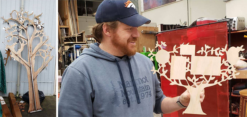 In the art world, the term for a scale model of a full-sized sculpture is “maquette.” The full-size tree will be 120” wide, with areas for projecting on during the show. Creating a scaled-down sample of the CAD design allowed Steve to test the concept, and to clean up some of the sharp angles created in the leaves in the original CAD file. Scaling the design up to the full size will be easy, now that the file is in the computer. VCarve Pro has a tiling function, so a single design file can be spread out among the several sheets of plywood that it will take to create the full-sized set piece. VCARVING OR ENGRAVING: V BIT
Using a V-shaped bit, the toolpath travels along the centerline of the design. The VCarve Pro software figures out how deep to plunge the bit in order to get the width that is necessary to carve the design. It is really more of a 3D file, since the Z depth changes as the width of the design changes. Steve found a Star Wars Aztec Calendar vector file online that challenged the program, but it machined very well, using the 60V bit included in the ShopBot started bit kit.
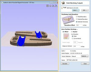
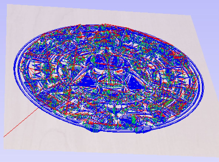 In this isometric view of the toolpath, the blue indicates where the V Bit has plunged deeper into the material to machine away the area between the design lines.
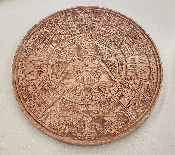 Where there is more space between the two sides of a closed vector, the V Bit plunges deeper. At the corners, the V Bit lifts up and out of the material, creating nice sharp corners. With all the of detail in this piece, this example took about 1 hr 20 minutes to carve. Then, the circle was cut out using a profile toolpath and a ¼” down spiral bit.
 Jerry from Moreno Valley College took a note from Mendocino College, and carved another version of the Star Wars calendar. The results look different because, in this version, the outer most circle is not selected.
3D CARVING: BALL NOSE BIT
The ShopBot CNC is capable of taking a 3D design file and machining it out of any number of materials in any size up to the table limits. This means that one can import an .stl, .obj, or other 3D file that may have been created for 3D printing, do a roughing pass (if necessary) to clear out the big parts, then do a finish pass with a ball nose bit to create the final 3D carve. While VCarve Pro does not support 3D CAD design, it does create 3D toolpaths (CAM) created in other software such as Fusion 360 or Solidworks. VCarve’s big sister, Aspire, does support 3D CAD using tools that are more suited to artists than engineers. One feature that it has is to create a 3D component from a photograph. To test this out, Steve and Dave posed for a photo on a smart phone, then imported the photo into Aspire to convert into a 3D component. After gluing up 3 layers of 1” pink insulation foam, Steve used a 1/8” ball nose bit to carve out the results.
 The 3D carving file created with Aspire was pretty impressive for a quick snap on a smart phone, then converting it into a 3D component. The file was carved in foam using a 1/8” ball nose bit. Using Aspire to create an underlying base, then using the 3D rendering to add details and texture could create more realistic results. An example of this technique can be seen in this blog post about a Master Class at a USITT regional meeting.
Students who take part in the theatre program at Mendocino College have the opportunity to practice set and prop design, sound and lighting, and costuming. The college puts on at least one play each year, alternating between musicals and dramas. The spring production will be Shakespeare’s “A Midsummer Night’s Dream” (hence the 120” wide tree.) The professional theatre is also available for outside productions, such as the dance company that put on the “Nutcracker.” After attending Mendocino College for two years, students can transfer their credits to a four-year program. Steve also intends to open up the production shop and create courses for students who wish to acquire CAD/CAM, CNC, and building skills for use in other professions and jobs.
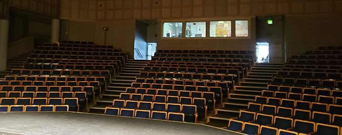 View from the stage of the theatre at Mendocino College in Ukiah, CA. Under Faculty supervision, students run the sound and light boards, build sets and props, and create costumes.
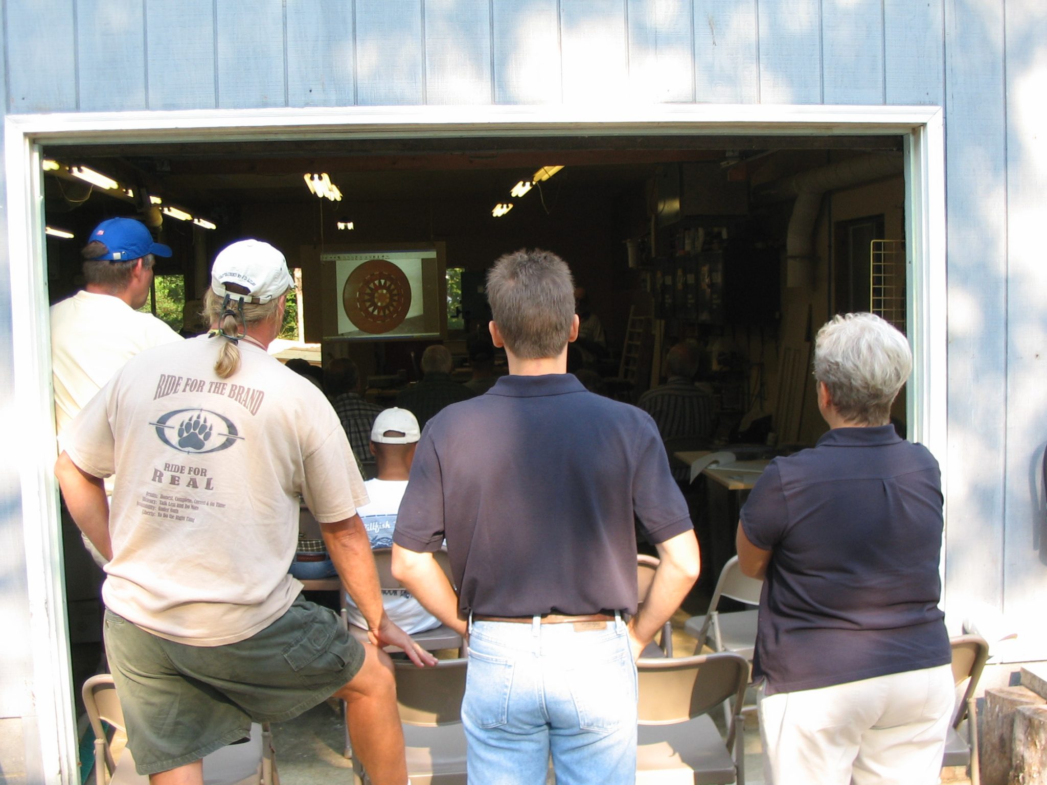
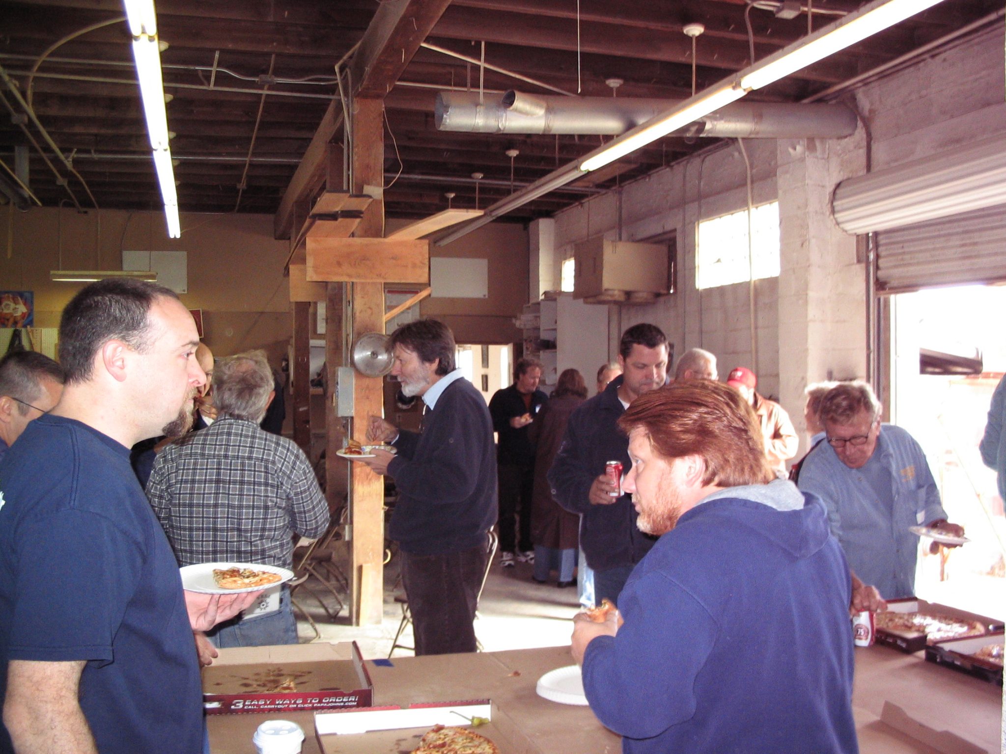
In March of 1999, a small group of ShopBot owners and other folks curious about CNC met in Bill Young’s shop on the coast of Virginia for the first of what was to become “ShopBot Camps.” Although these informal gatherings of ShopBot owners were sponsored by ShopBot, they were never intended to be sales tools, but simply a gathering of folks with a similar interest… making things with a ShopBot.

Although each one was unique, they almost always included a couple of presentations by ShopBot luminaries on topics like what’s new at ShopBot and cool projects they had worked on or heard about. At the heart of the gatherings is always the attendees sharing what they had created or what they wanted to create. It was networking before networking was a thing!
The camps program has faded over the years but the interest and need never did. With that said, we want to breathe some new life into camps and are starting to collect names of people that are interested in hosting one in their area. The only real requirements are that you have some flavor of ShopBot, that you have room for 15-50 people, and that you might enjoy having strangers take over your shop for a day. We’ll spring for something tasty for breakfast and lunch, pay for renting whatever extra chairs etc. that you need, and will send someone to be ringmaster… maybe even Bill. As a bonus, it’s a good excuse to clean your shop up just a little!
If your shop won’t work for a camp (or you really just don’t want to clean it), but you’re still interested in being a host, maybe you know of a local business that might be a good venue: a restaurant with a big meeting room, a local makerspace, or a school with a ShopBot, to name a few. Get in touch and we’ll see what we can arrange. If this sounds like something that’s up your alley, get in touch with us at campshopbot@gmail.com with a few details, where you are, what you do, etc. and we’ll add you to the list.

If you’re not familiar with ShopBot Camps, you can find a pile of camp reports here on the ShopBot blog: http://www.shopbotblog.com/category/campshopbot/
By ShopBot, October 17th, 2019 Blog post written by Walter Dill
————————————
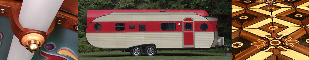
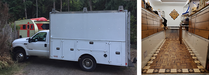
First, a little backstory about Walter Dill and Monica Uhl, aka DillUhlsional: Soon after our relationship began 7 years ago, Monica realized that together we are DillUhlsional, which is appropriate since we have hugely grandiose plans! 5 years ago, with significant support and editing from Monica and a few others, I had a successful Kickstarter campaign which helped acquire a ShopBot Desktop CNC router. The main project after fulfilling all 172 Kickstarter rewards has been customizing this 30’ 1956 Airfloat Land Yacht (Talulah) and outfitting our 1999 F450 7.3L diesel box truck (Clyde) to be our studio/gallery/woodshop/tow vehicle. Keep your eye out for future blogs about the various elements in both Talulah and Clyde that were made possible by the ShopBot Desktop.
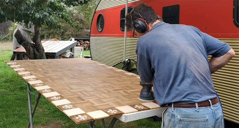
The project that is featured in this blog post is the parquet floor or “truck floor de lis” for our mobile workshop
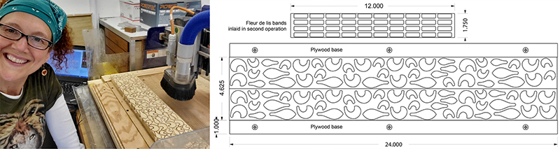
We were recently offered 2 boxes of very nice solid hardwood parquet flooring which had been acquired a few years ago at Habitat for Humanity. The unopened packages were stamped “Ernst Hardware” which had gone out of business 23 years ago. Note: Monica started learning CAD, VCarve, and running the ShopBot with this project.
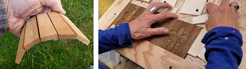
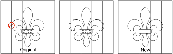
There were nearly enough parquet panels to cover the 4’ x 12.5’ truck floor. A few panels resembled walnut. The others were lighter and looked more like a variety of mahogany. All had a very spicy smell – probably of Asian origins. We created a dark and light checkered perimeter using the squares of the dark wood alternating with a thick veneer birch plywood that was exactly the thickness of the parquet panels (1/4”). We chose to inlay a classic fleur de lis into the dark panels. The drawing below was used in VCarve Pro to make the inlays.

Drawing: Rhino3D CAD was used for all drawings. VCarve Pro is also capable of this type of drawing but doesn’t have the versatility of a full-blown CAD program. There are multitudes of fleur de lis variations on the internet. We adapted this version to fit the square format. The strategy was to make 6 separate parts for the “petals” (see drawing below) so the grain goes in the general direction of the petal.
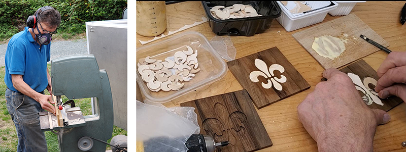
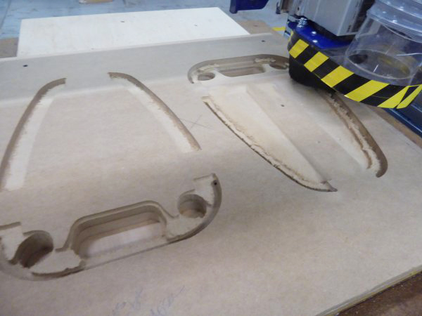
Hold down and begin routing: The individual panels had a paper backing and needed to be glued between the connected strips to make a solid board for routing. When glued up, there were subtle variances in dimensions and flatness. Therefore, we placed three at a time on the router table and kept them in groups of three and in the same order to ensure accuracy in the subsequent operations. Wedges secured the panels. The image (below right) is setting up for the second operation, to clean out and trim the outline with a 1/16” bit.
Redesign mid-stream/hindsight: After cutting all 45 inlay openings we realized that the larger petal needed to be a bit wider for aesthetic reasons (see drawing below). We placed the panels, in their sets of three, back in the router and trimmed the petals slightly larger.
Cut inlay parts: The 24” x 4 5/8” maple board was glued to a plywood base which extends to either side. (See drawing). This allows the workpiece to be screwed down to the spoil board with the screws being totally outside of the cutting envelope.
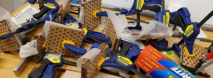
After routing, the parts were sliced off with the bandsaw using masking tape to hold the parts from falling into the blade. (Hint: if you haven’t already tried this, it’s a good trick.) The parts are then glued into the openings (below right) and clamped together (bottom).
Cut and inlay the “band”: The last inlay part cleans up the lines and is the finishing touch for the fleur de lis.
The glue-up: The completed parquet panels were first glued onto 1/8” plywood because the truck floor was not perfectly level. A 4’ x 8” sheet, about 2/3 of the floor, was prepped outside on a worktable using clamps and bricks for weights (below right).

Sanding, sanding, and more sanding: This is less than 2/3 of the final floor! The remainder was glued down in place. Then more sanding and sanding.
The finish: We have sealed the floor with Daly’s Ship and Shore to get the warm tones and will be applying Bona Traffic HD water-based whence the sealer is cured.
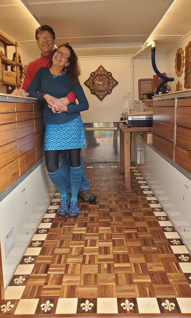
Now the ShopBot Desktop has a nice floor beneath its feet. See more pictures of the truck and trailer at https://www.dilluhlsional.com/airfloat.
_________________________________________
For questions or to get a free copy of the VCarve files for this fleur de lis contact: Walter Dill – walter@dilluhlsional.com and/or Monica Uhl – monica@dilluhlsional.com
By Sallye Coyle, October 16th, 2019
This blog post originally appeared on the 100k Garages blog in 2017. I often get requests for information regarding two-sided machining on a ShopBot tool and figured with that many people asking about it, that we should cross-post it here on the ShopBot blog for additional accessibility. I have edited a few things to account for updates in later versions of the Vectric software.
_______________________________________________
A good friend recently sent me a Solidworks file, and asked about machining it on a ShopBot. I don’t have Solidworks on my computer, so I requested and received the model as an “.stl” file. The model could have just as easily been created in Inventor, Rhino, Fusion 360, or any other 3D rendering software/scanner.
Since I do have Aspire CAD/CAM software (VCarve Pro’s big sister software), I imported the .stl (component or 3D model) twice (inside and outside) so I could plan my strategy. I originally wrote this blog using VCarve Pro v. 8.0, which was fully capable of doing all the machining. Vectric software v. 9 and above give you the option of setting up a two-sided file, so that would eliminate some of the steps outlined below. One caution: With VCarve Pro, you can only import one component at a time. That would work for this application, since the “Inside” and “Outside” of this project need to be treated as separate CAD/CAM files.
The photo below shows the finished result. At the end of this entry, I have indicated how I would charge for a project such as this.
Steps to Examine the Model
- Use the tools under the Modeling tab to import the 3D model into the Vectric software.
- If using Aspire, import the .stl twice, once for the “Inside” and once for the “Outside.” If using VCarve, open up two sessions to import each side one at a time.
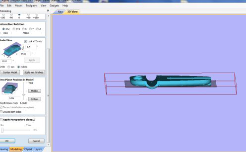
- Use the “slider bar” on the import page to determine where to slice each model to get all the details on each side.
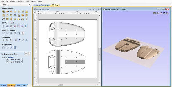
- The total thickness of the model is 1.5″ but each side needs to be machined to a depth of 1.1″. Since the midpoint of the material is only .75″ and each side goes deeper than that, it is best to treat the two sides as two different models.
- See HELP in Aspire/VCarve for terrific instructions on how to do this (this blog entry also gives a few more details).
Givens:
- The project was going to require two-sided machining.
- Two samples were needed to complete the large seat bracket (~15″ tall and 1.5″ thick per sample).
- The customer didn’t specify any requirement for material.
- The material needed to be exactly 1.5″ thick so that the inside and the outside of the sample would line up correctly.
Thinking Through the Project
- Gluing up two pieces of 24″ x 24″ x .75″ MDF would:
- Fit two completed samples onto the material.
- Be a more consistent thickness than plywood.
- Fit on a number of different sized ShopBots (Desktop MAX, Buddy, Gantry).
- Letting the store cut a 2′ x 4′ x .75″ piece of MDF in half crosswise would save having to do it at home.
- Gluing the two pieces together with wood glue and letting them dry would make up a board 1.5″ thick.
- Purchasing a dowel at the same time would help with the registration of the board for flipping.
Setting Up the File and Materials for Two-sided Machining
- Set X, Y origin in the CAD file to the middle of the material.
- Set Z Zero to the top of the material.
- Decide how to flip the material (horizontal or vertical).
- Use 4 dowels as registration markers.
- Start with a temporary spoil board attached to the table, and machine the dowel holes and center point into the temporary spoil board.
- Indicate in the CAD file where to put hold down screws in the temporary spoil board, and in the actual material.
- Attach the actual material to the temporary spoil board, then machine the center point and dowel holes into side one.
Prepping for “Inside” Machining (File #2)
Analyzing the file, observe that some sections need to be created as a 3D (simultaneously moving 3 axes) file. However, much of this side can be machined with 2D toolpaths (plunge the Z and then machine at that depth), which will save time and give better results.
- The rounded slot needs to be a 3D file, machined with a ball nose bit.
- The center pocket has sharp inner edges, so should be pocketed with an end mill.
- There are marks to indicate where to use a small drill bit to drill after machining.
- The model can be partially cut out from this side.**
- There are registration guidelines that need to be generated.
- Holes that allow dowels to fit.
- Hold down for base board and material.
The Big Picture
- In Aspire, under Model > Scale Model Z Height, observe that the deepest cut on this side will be 1.1”.
- The material is 1.5” thick, so cutting more than .75” will go more than halfway through the material.
- Note: If the vectors are available from the original file, import them at the same time and overlay them on the 3D model.
- If only 3D data is available, create a vector boundary (modeling tab) around the entire component to define the edge of the model.
- Add some vectors (drawing tab) over the model to indicate where to use pocket, profile, and drill toolpaths.
- Create a second Copy and Mirror the model and vectors, and Center both of them in the material.
- Add registration and hold down vectors, and center them in the material.
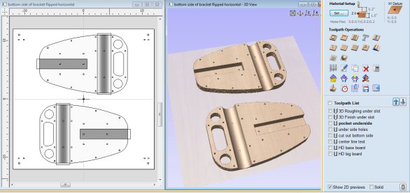
Creating Toolpaths for “Inside”
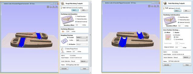
3D Toolpaths
Open the Tool Database (Library) and, if necessary, create two .25” ball nose bits. Start with any ball nose bit, Copy it, and change the name and specifics of the new bit to reflect its use:
- For the roughing bit, set pass depth to .25”; stepover to 40%; and feed rate to 4 and 1 ips.*
- For the finish pass bit, set stepover to 8 – 10%: and feed rate to 6 and 6 ips.*
- Use the roughing bit to create a roughing pass to clear away most of the material by stepping down in .25” increments.
- Use the finishing bit to create a finish pass to result in a smooth, rounded channel.
*These values are good for the gantry tools (wood).
- For Desktop tools, try 3 and 1 ips for the roughing pass and 4 and 4 for the finish pass.
- For a Handibot, try 2 and 1 ips for roughing, with a pass depth of .2, and 3 and 3 for the finish pass.
2D Toolpaths

Specify a .25” end mill bit:
- Pocket to a depth of .84” the flat channel (depth determined in 3D model).
- Profile to the inside the through holes (.75” deep or halfway through).
- Drill the underside holes to a depth of .1” (just as a marker).
- Profile to the outside edge of the model (.75” deep).**
Registration Holes and Hold Down
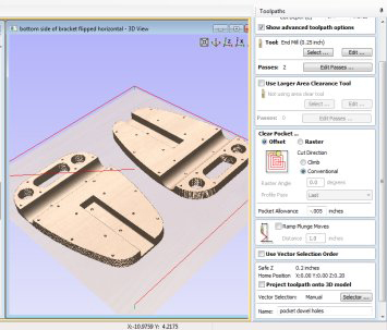
- The dowel measured .5” in diameter.
- Use the Pocket Toolpath option to create a depth that would fit the dowels.
- The registration hole for the dowel should secure the material in the correct location for flipping yet leave some leeway (allowance) to easily get the dowel in and out of the hole.
- To see the Pocket Allowance option, make sure that Show advanced toolpath options is checked.
- A negative allowance makes the hole bigger.
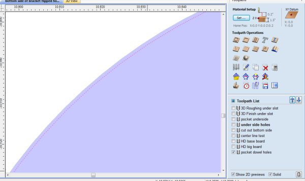
- After calculating and closing the toolpath, ensure that the allowance has made the hole larger rather than smaller. Checking the Solid option at the bottom of the toolpaths screen (or the wireframe/solid at top of page in v.9.5) shows what the bit will actually remove. Zoom in on a dowel hole to see that the bit is traveling slightly outside the drawn vector.
- Hold down markers are created using the Drill routine to a shallow depth.
- These toolpaths are used on the temporary spoil board, and on the first side of the material.
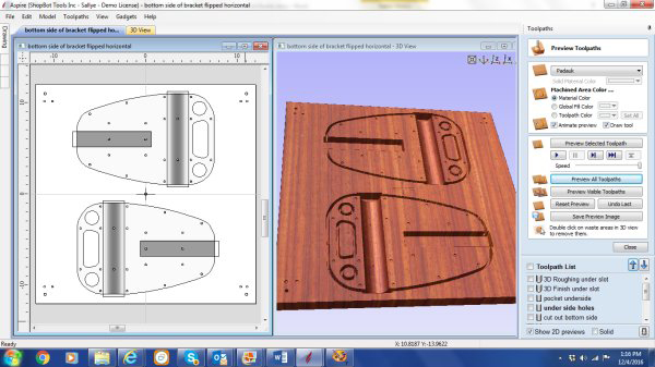 Simulation of the “Inside.”
Prepping for “Outside” Machining (File #3)

Most of this side needs to be treated as a 3D (simultaneously moving 3 axes) file. Only the final cut out will be a 2D profile-to-the-outside.
- Since the bit is a rather large ball nose bit (.25” diameter), one could probably get away with not making a roughing pass. But, there is a rather deep section in the “Outside” holes, so it is better to be cautious.
- Set the finish pass to run very quickly, since it is only taking off a bit at a time.
- The final cut will be to separate the model from the substrate, using a 2D profile-to-the-outside toolpath.
The Big Picture
- First thing is to prepare to line up the ”Inside” and “Outside” models with each other.
- Copy the vector information on placement and hold down from the “Inside” CAD/CAM file, and Paste it into the new “Outside” CAD/CAM file.
- Mirror the vectors, and note how they were mirrored to know how to flip the board.
- Import the “Outside” 3D component and locate it into the vectors. In Aspire, under Model > Scale Model Z Height, one can see that the deepest cut on this side will be 1.02”.
- The material is 1.5” thick. Be aware of how deep the toolpath goes when 3D machining the second side so that the model is not separated from its substrate.
- Offset to the inside of the vector around the entire model to define the edge of the model for the first 3D milling.
3D Toolpaths

Specifying a .25” ball nose bit:
- Create a roughing pass to clear away the material in the deeper areas.
- To avoid breaking through the material, use the inside (offset) vector to define the scope of the finish pass.
- To finish off the 3D rounding of the edges of the “Outside” side, create another 3D toolpath that runs between the inside offset vector and vector at the edge of the model.
- Cut the parts loose with a final 2D profile-to-the-outside toolpath set to slightly more than halfway through the material.
ShopBot Set Up
- If necessary, surface the spoil board to ensure that it is flat under the material.
- Use the automatic XY Zero routine (icon or C3) to zero the X and Y at the lower left hand corner of the table.***
- Use M2, 12, 12 to move the bit to the center of the 24” x 24” material.
- Zero the X and Y there (Z2).
- Insert the .25” end mill bit into the spindle/router collet.
- Place the temporary spoil board in location.
- Use the Z-Zero Plate to zero the Z to the top of the temporary spoil board.
- Run the ShopBot part file (.sbp) file to mark the location of the hold down screws.
- Screw down the temporary spoil board.
- Look to be sure the temporary spoil board is flat against the ShopBot spoil board.
- Re-zero the Z at the top of the temporary spoil board.
- Run the .sbp file to indicate the center of the spoil board.
- Run the .sbp file to create a pocket for the dowels.
- Test that the dowels slide into the holes easily.
- If the dowels are tight in the hole, rewrite the file to make the hole slightly bigger.
Place the Real Board into Position
- Zero the Z to the top of the real material.
- Run the .sbp file to locate the hold down for the material.
- Screw down the board and check that it is flat against the temporary spoil board.
- Rerun the Z Zero file to the top of the real material.
- Run the .sbp file to create a pocket for the registration dowels. You may have to make them deeper than you did for the temporary spoil board.
- Test that the dowel will fit in its hole easily.
- Note: Dowels themselves should be long enough to jut into the board when it is flipped, and short enough to let the flipped board sit flush against the temporary spoil board.
Running the Files
- When machining the first side (“Inside” in this example), the hold downs outside the model should be sufficient for all the work.
- Remember to zero the Z whenever a bit change is made.
- When machining the second side (“Outside” in this example), there will come a point when the hold downs outside the model will not be sufficient to keep the model in place.
- To secure the model for the final machining, AFTER the first 3D finish pass is complete, secure the model to the temporary spoil board using long screws through the two holes in the “Outside” of the model.
Results
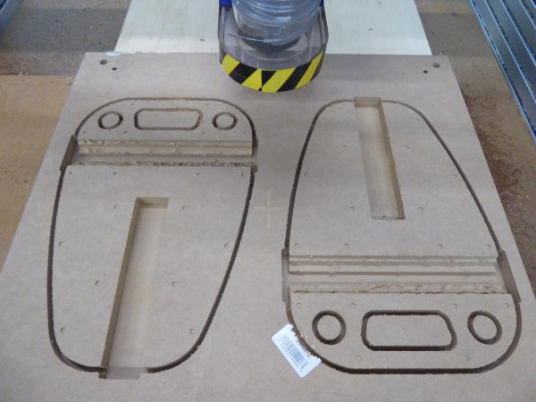 These parts were machined on a ShopBot Buddy® (32″ x 24″ cutting area).
- All the 2D machining with the .25” end mill for the “Inside” of the model is complete.
- Since the roughing pass is a pocketing pass that will be smoothed over in the finish pass, it has been run with a .25” end mill bit rather than the .25” ball nose bit.
- Dowels are ready to be put into position so the board can be “flipped.”
- The board has been unscrewed from the temporary spoil board.
- The 3D machining (.25” ball nose bit) on the “Inside” of the model is complete.
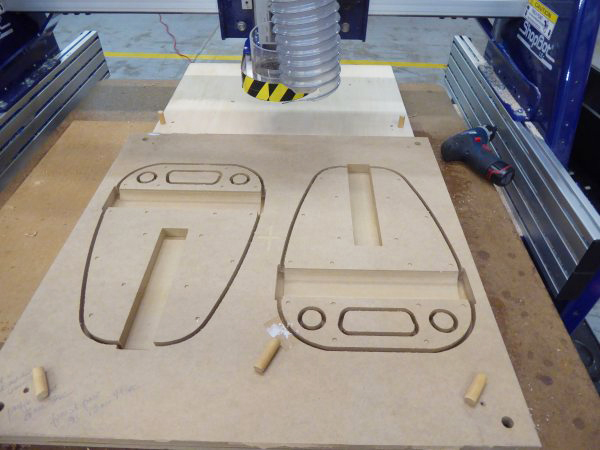
- Roughing pass on the “Outside” is complete (.25” ball nose bit).
- Note that the large holes at the top of the model are now completely open and waiting for their smooth over.
- Finish pass started (.25” ball nose bit).
- After this part of the machining is complete, long screws through the holes in the center of the models will be used to hold down the models while the models are separated from the substrate.
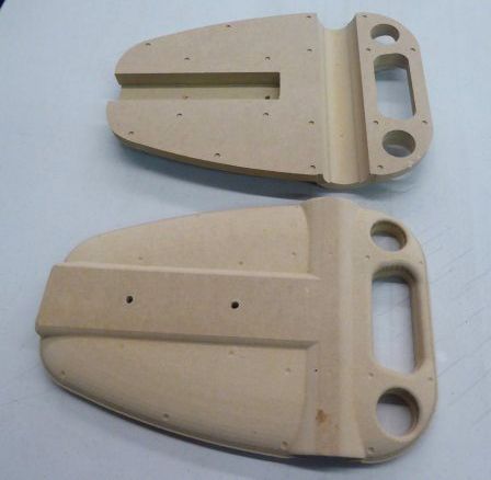
 Completed samples viewed from the inside and the outside of the seat bracket.
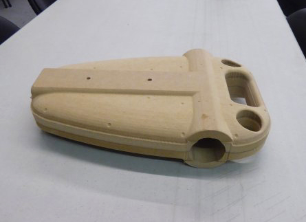 The two sides fitted together.
**What Would I Do Differently?
Design time: It would have cut down on my design time if I had asked the customer to send the vectors that made up the original 3D model (.eps or .dxf format) in addition to the 3D model itself (.stl format). As it was, I had to use the tool in the Vectric software to define the edge of the component, or redraw the vectors I needed over the 3D component.
- In Solidworks, one can select the vectors from the model, and use SAVE AS to export them as 2D files (example: .eps, .dxf).
- In Inventor, one can choose to view the model from above, then hover the cursor above the 3D rendering. When the vectors are visible, right click to see the option to save as or export the vectors in .dxf format.
Toolpathing options: I would think through more carefully how deep to make the tool paths that go along the edges of the model. If I had made the 2D cut out on the first side I machined shallower (the “Inside”), then I would not have had to create two separate 3D finish passes near the edges of the second side (the “Outside”). I would still put hold down screws in the center of the “Outside” pieces so that the work did not shift when I ran the final profile to cut out the samples.
*** Setting Up the XY Zero Routine
If the automatic XY Zero routine using the proximity switches has not been set up on the ShopBot, now is a good time to do that. In the ShopBot Control software, click on Tools > ShopBot setup. Click through the screens to find the page that talks about setting up the XY Zero routine. Choose “Make it easy on me.” The program will let you use the keypad control to move the bit to where you want 0,0 to be and zero it there. (Click on the fixed distance button on the keypad to fine tune movements of the ShopBot.) Then, the program will test the distance between the 0,0 point and the proximity switches, and make it so you only have to use C3 or the icon on the position screen to zero the X and Y.
This is critical if you need the 0,0 to be absolutely accurate. By using the automatic X,Y Zero routine to give you a good starting point, then moving the bit to an exact location (M2, 12, 12) and setting the new zero there, you can always get back to that point in case of power failure or operator error.
Suggestions: How to Charge for a Project Like This
Although I did not have to create the original model, the expertise to figure out how to machine the model, and the cost of owning, maintaining, and running the shop and equipment to be able to do such a project should be taken into account.
- The materials (purchase and prep) and the bits all have to be covered.
- Shipping costs where applicable also have to be considered.
- I usually charge between $75 and $125/hour for design time and machine time (setup and clean up are also added to the actual machine time).
- For this project:
- Design time: Approximately 2 hours.
- Time to purchase materials and glue up board: approximately 1 hour.
- Actual time the ShopBot was running:
- Marking Hold Down of temporary spoil board: 0:00:15
- First attempt at holes for dowels on temporary spoil board: 0:00:24
- Redoing holes for dowels: 0:00:24
- Marking hold down of material: 0:00:15
- 2D files for side 1: 0:12:03
- 3D files for side 1: 0:13:04
- TOTAL SIDE 1 (Inside): 0:26:24
- Roughing pass for side 2: 0:20:00
- Finish pass for side 2: 1:20:25
- Final finish pass for side 2: 0:08:24
- Cut out the parts from the substrate: 0:03:00
- TOTAL SIDE 2 (Outside): 1:56:49
- Additional time added for set up, bit changes, clean up, etc.: Approximately 1.5 hours, including surfacing the ShopBot Buddy® table prior to machining the parts.
Tools in Vectric Software to Help Estimate Job
Compare estimate to realtime.
By Jennifer Nix, September 10th, 2019 On Saturday, August 24th, ShopBot Tools held their first Open House in Durham, NC. The event was free and open to the public, but because it was our first time holding one we weren’t sure what to expect. Little did we know, we would have over 200 people come see us during the 4-hour event!
Our full line of tools were on display for the Open House. Everything from our smallest tools, the Handibot® Smart Power Tool and the ShopBot Desktop, to our more specialized tools like the 5-Axis tool and Standalone Indexer. The newest tool in our line-up, the Desktop MAX ATC, was in operation showing off its capabilities by cutting a full-sized guitar body out of a block of mahogony. Our Edge Clamp Joinery Jig showed people how they are able to create precise, repeatable dovetails and joints, while also showing off the creativity one can achieve with decorative end-milling when using the jig in conjunction with the Desktop and Desktop MAX. The precision and versatility of ShopBot tools were being showcased for all that cared to look and learn.
Other tool demos involved the participation of our visitors, with some even providing an opportunity for the users to create something to bring home with them. Kids and adults alike were able to make their own badges, cut marble puzzles on the Desktop tools in our training area, draw graffiti with the help of a Handibot, and even make their own personalized chocolates. Sometimes it was difficult to tell who was having more fun, the kids or the adults!
In addition to ShopBot’s tools being on display, there were many employees at the event available to provide some in-depth tours, as well as answer questions that anyone might have about the tools and the company.
There were several raffle prizes available, including free Basic Training sessions here at ShopBot, expansive digital vector clip art libraries, and a variety of items that were cut by our own employees using our tools. Who knows what you could win when we do our next Open House? Keep your eyes out for an announcement about another one some time next year and make plans to join us.
Take a look at some of the photos from the event:
By Sallye Coyle, September 4th, 2019 Fusion 360, a powerful cloud-based CAD/CAM software that is free for educators, has been gaining popularity in schools because the design files can be output to multiple digital fabrication tools such as CNC machines (like ShopBot tools), laser cutters, and 3D printers. While the price is right, sorting through the possibilities and keeping track of the design flow can be daunting for both new and experienced users of CAD/CAM software and ShopBot CNC machines. With this in mind, ShopBot’s July session of the Digital Fabrication for Educators workshop, led by Sallye Coyle and David Bryan, worked through Fusion 360 with a group of willing and patient educators.
There was a 3D printer and a laser cutter present at the workshop, but a big part of the event was for everyone to get hands on experience with setting up a CNC for machining. Whether new to the process, or with a couple of (months/years) under their belt, everyone went home with new tips and tricks for CNC use (and VCarve Pro).
Getting Started: A “Simple” Open-Faced Cube
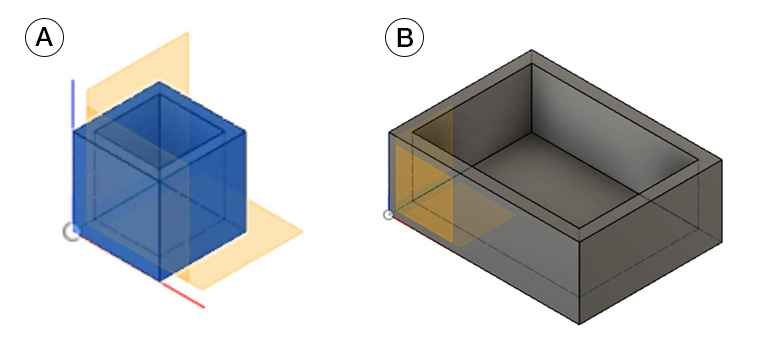
Fusion 360 is an engineering-based 3D rendering program. Translation: Start with a 2D drawing or “sketch” on a plane or face (X, Y, or Z axis), then extrude it into a 3D rendering or “body” that can be viewed and manipulated from multiple angles on screen. Many tools in the drop-down menus (Sketch, Create, Modify) allow the user to create and manipulate models.
To create a 1” cube with an open face, one could start with drawing a rectangle with fixed dimensions in two axes (X and Y: Sketch menu). Then, extrude the cube into the Z dimension one inch (Create menu). Using the “shell” tool under the Modify menu, make the solid cube into an open-faced cube with walls that are .125” thick.
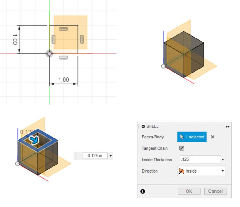
The resulting 3D model can be exported as an .stl for 3D printing or 3D carving on a ShopBot or other CNC machine. Alternatively, the 2D sketch (X and Y) of the top face with the outside and inside edge of the cube could be exported as a .dxf for use with the ShopBot. In that case, the Z dimension would be created in the toolpath option (profile or pocket) rather than taken from the 3D body itself.
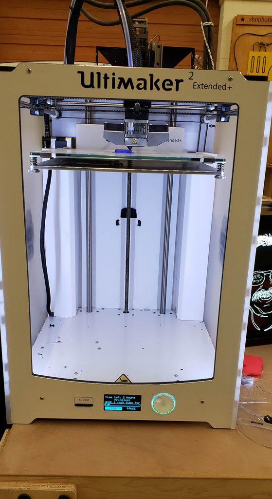 3D printer starting on the 2+ hour print of the 1” cube. Parametrics
A power of Fusion 360 is that it is parametric. Translation: instead of being dependent upon a fixed value for a dimension or parameter, one can create a “User Parameter” for the dimension. If the value of the User Parameter changes, the entire model will change accordingly. Table 1 (below) shows the original dimensions set for creating a 1” cube (bottom), and a set of User Parameters defined for the Width_X, Depth_Y, Height_Z and Wall Thickness of the cube (top.) Table 2 (below) shows how the model changes when the original dimensions are replaced with the User Parameters. It makes updating the model extremely easy. Think of building slotted furniture and being able to change the slot size (and cut depth) to reflect the actual thickness of the plywood by simply by changing the value of the User Parameter.
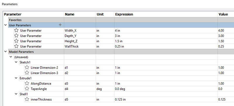 Table 1: Fixed Model Parameters defined in initial cube. User parameters are defined for future use. 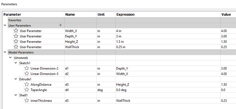 Table 2: Fixed parameters replaced with User Parameters. Note Expression and Value changed from Table 1.
 A) 1” cube with Fixed Parameters B) Cube resized with User Parameters 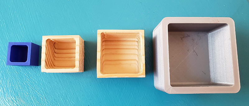 The samples above are made with a single “component” (open faced cube.) The sizes are manipulated by changing the values of the “User Parameters.” Objects in blue or grey filament are 3D printed. (Time to 3D print the 1” cube at high quality: 2Hr 20 min.) Models in wood were machined on a ShopBot Buddy® from a 2” x 6” board, using the CAM features of VCarve Pro. [Time to hollow out both cubes from either 3D .stl (roughing and finish pass toolpaths) or 2D .dxf (pocket toolpath) and cut out the cubes (profile toolpath): 10 – 15 minutes total, both cubes.] Fillets in the corners can be added in the Sketch mode, the Create mode, or are a result of machining inside corners with a round, rotating bit. Preparing 3D models for 2D laser cutting or CNC machining
Fusion isn’t just for 3D printing (additive) or 3D carving (subtractive) of models. It is also very useful for creating and inspecting the model in its 3D rendering, then preparing the various faces for 2D cutting of sheet good materials.
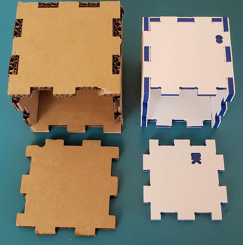 In the photo above, a finger-joint box is rendered in 3D, then the 2D sketches of each face have been exported for cutting out of cardboard on the laser cutter. The white and blue cube was machined out of ¼” King Color Core HDPE on a ShopBot. User Parameters were used to change the size of the models.
In the files created for the ShopBot, “dogbones” were added to the internal corners to account for the fact the closest a rotating round bit can get into an internal corner is the radius of the bit. Adding a bit more space to the internal corner means a square corner can fit into the finger joint. An add-in developed by Brian Ekins makes adding the dogbone to a Fusion 360 model as easy as clicking on the model and defining the diameter of the bit. Adding “Components” in a Fusion Model
The first example of an open-faced cube for 3D printing or CNC machining out of a block of material is relatively simple because there is basically one part in the model. In contrast, a finger-joint box that is cut out of sheet goods is made up of several different sides. In the photo below, the open faced box has 5 different pieces: a top, a front, a back, and 2 sides. The design must take into account that the joints on the edges are not all the same because each face must fit into its corresponding joints. Top and bottom (if there was one) would be the same, Left and right have the same joints, but are mirrored from each other if the inside and outside are not interchangeable. Likewise, the front and the back have the same joints, but are mirrored from each other.
One way to keep track of the different parts is to separate them into different components. The term “component” has different meanings in different software, but for Fusion, it’s easiest to think of a component as a “level.” A component can have, within it, Sketches, Bodies and CAM set ups. It can be turned on and off to make it easier to see what one is doing. Fusion treats a “Body” differently than a Component. However, one has the ability to convert a Body into a Component to help keep track of the various parts and pieces. Yes, it is a lot to process.
 Examine each side of the above model. The joints on the edges are different for each piece, though the sides and front/back are mirrors of each other.
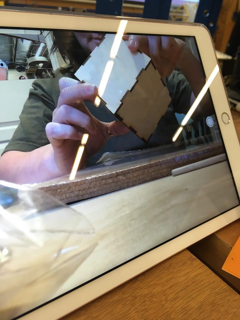 Once a 2D .dxf file has been created from the 3D rendering, it can be sent to a laser cutter remotely. Heather (visiting ShopBot in Durham, NC) sent the finger joint box file to her sister in Utah, who cut it with a GlowForge laser cutter. CAM with Fusion 360
One big difference between Vectric software (like VCarve Pro) and Fusion 360 is in setting up for the CAM (manufacturing) with a CNC machine like a ShopBot. The first question that Vectric software asks when one opens a new CAD file is “what is the size of the material,” as well as the origin of the X and Y axes and the Z axis origin. That information is carried throughout the entire design and toolpathing (CAM) options. In 2D toolpathing (profile, pocket, drill) the Z or cut depth is defined by the user. In 3D toolpaths, the Z or cut depth is defined by the 3D model.
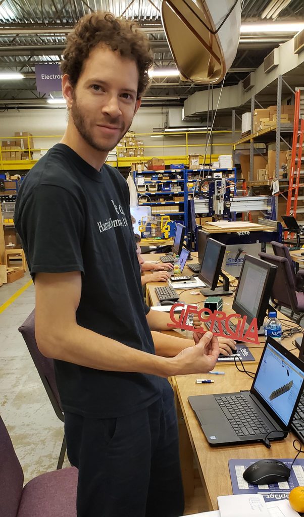 Chris came into the class with more experience in the CAD side of Fusion 360, and used the workshop to get more familiar with the CAM side. He imported the “Georgia” as a bitmap into Fusion 360, then drew the vectors. He discovered that it might be more efficient to trace a bitmap in another software rather than hand following in Fusion 360. In Fusion 360, one does not define the material, the origins, or how the parts fit onto the material until all the components have been designed. In its default mode, the Y axis is up, so one has to define Z as up in preferences. For the most part, Z depth is defined by the model. Paying attention to where the software is defining the start point of the model is critical. Preview the toolpath before writing the ShopBot code, read the code, and do an air-cut to avoid mistakes. And do make sure that the Z axis on the ShopBot is set up the same way as it is in the code so that the bit doesn’t plunge too deep into the material, or ride above the material, when actually running the file.
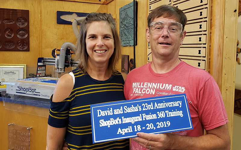 David and Sasha chose to celebrate their 23rd Anniversary by attending the class. David works with robotics students, and prefers Fusion 360 as the design software because of its engineering base and parametric qualities. He wanted more hands-on time with the ShopBot. Sasha is principal of an elementary school, and wanted to learn more about digital fabrication in general. Yes, this was a class with an emphasis on Fusion 360, but they ended up creating their final sign in VCarve Pro. It wasn’t until they were showing off their sign to their sons that they discovered their mistake. The design and toolpathing is perfect. However, the month was July =) __________________________________________
A note about the workshop leaders
Sallye is fluent in Vectric software (VCarve Pro, Aspire), which is more graphic-based (think artists and signmakers) and, to her mind, more intuitive for beginners. While there are always tricks to be learned/taught, the basic workflow of CAD (what and where), to CAM (how), to creating files for the ShopBot, can be demonstrated fairly quickly in the Vectric software. For Sallye, working in Fusion 360 has been like learning Russian when her first language is Spanish: she can now maybe order a meal, or go grocery shopping, but actually having a conversation that includes jokes or writing a short story will require more practice and tutorials. Thank goodness for YouTube videos, especially Lars Christensen, Taylor Stein and Jim Yost. She pays attention to the little asides that experienced users assume that newbies will know. Sallye is looking forward to getting more CAM tips at the upcoming Fusion Academy in Portland to expand her knowledge of Fusion 360 for 3, 4, and 5 axis machining.
David has a background in Solidworks and Rhino, engineering-based 3D rendering programs. So Fusion0 360 is not quite as great a leap. He is also more fluent in 5 axis machining, since he has been working with the ShopBot 5-axis tools.
A big thank you to the patience and sense of humor of the first group to attend a Fusion 360 training while Sallye and David worked through what can be accomplished in a 2 + day workshop. We learned a lot! Let us know if you’re ready for another Fusion 360 workshop at ShopBot.
By ShopBot, August 8th, 2019 Reported by Chris Burns
The National Association of Music Merchandisers holds two conferences every year. The Summer NAMM show in Nashville, TN is filled with people from all different areas of music including musicians, audio technology experts, and instrument makers, just to name a few. Some of the businesses exhibiting build hundreds of instruments every day, such as Martin, Taylor, Fender, and Gibson whereas others are small builders that put out only dozens each year. This year at the show, ShopBot exhibited for the first time and debuted the new Desktop MAX ATC with a 6-tool automatic tool changer. It was a big hit among both large and small luthiers. We were also displaying a small Becker vacuum pump and template with three cutting stations. The larger 36” x 24” cutting area of the Desktop MAX can fit a body, neck, and fingerboard and still have room for pickguards, bridges, and pegheads.
Here are some highlights from the show:
- Tim Teel, Director of Guitar Design at Martin Guitars, stopped by the booth to see the new tool and was delighted with the size and the performance of the MAX ATC (even though we were cutting Les Paul solid bodies). Martin uses several ShopBot Desktops for cutting inlay and special parts in their development area in Nazereth, PA. I must confess I returned to the Martin booth several times to play their D-18 Modern Deluxe. Tim explained the new innovations that make this an amazing instrument. “Some ultra-modern features include a titanium truss rod, liquid-metal bridge pins with red dots, and a composite carbon fiber bridge plate that boosts volume without adding weight.” Not bad for a company that has been around since 1833. All I know is that I did not want to put it down.
- Local Nashville musicians, Kasey Tyndall and David Dollar, stopped by to play some songs in the ShopBot booth. David brought his Elliott Tonemaster that was cut on a ShopBot Desktop a few years ago.
- Will MacFarlane drove up from Muscle Shoals, AL to jam for a bit in the booth. Will was inducted into the Music Hall of Fame in 2012 as a friend of the Muscle Shoals Rhythm Section and has appeared on dozens of albums with the likes of Etta James, Bobby “Blue” Bland, Little Milton, Levon Helm, and Lenny LeBlanc. He also toured with Bonnie Raitt for years as her lead guitarist.
- The ShopBot booth happened to be located just behind Chris Mitchell and the gang of gifted luthiers and musicians from Pladd Dot Music. They have been cutting their CMG guitar line and Devilcat amps for around five years on a larger ShopBot tool. We even had time to slip in some Vectric 3D training while we were together.
We were helped in our booth by longtime ShopBotter Ray Clark from Teen Challenge Women’s Ministries in Jackson, MS. Ray oversees four large PRSalpha machines (two with ATCs) that all run 40 hours/week providing job training for women recovering from substance abuse. They produce encouraging hand-painted plaques and religious themed items that are sold in several states to help support the 13-month residency program, that is provided free of charge, to the people they serve. Please visit their website to learn more, and maybe even consider helping in some way.
A very special thanks to Andy Elliott at Elliott Guitars for building such incredible instruments and loaning the ShopBot built guitars and equipment for our booth. Also, a big shout out to my friend Bob Thompson of Thompson Handcrafted Guitars in West Virginia for building my Curly Koa Dreadnought guitar. I love it! You are both gifted craftsmen with a passion for giving much more than expected to your customers.
But the best part of the show for me was spending the weekend in the booth with ShopBot’s first employee and legend, Gordon Bergfors. Gordon has had an incredible impact on the company over the last 23 years and has had his hand in every aspect of the design and manufacturing of the electronics, the software, and the hardware. Next to CEO Ted Hall, no one has contributed more to your CNC machine. He is now retiring from office work to pursue a life of digital fabrication leisure (yeah right). Thank you, Gordon, for all you have done with your time at ShopBot!
__________________________________________
Chris Burns is a digital fabricator from Durham, NC and works part-time for ShopBot upgrading, assembling, and training on new and used machines all over the country. You can follow Chris’ travels on Instagram at @chrisburns981.
By Jennifer Nix, May 16th, 2019 
Hone your craft. Build your brand. This was the idea behind Spring Make 19 in Cleveland, Ohio April 25th – 27th. As a first time sponsor of the event, we weren’t quite sure what to expect, but things got off to the races quickly!
The first day of the event, Thursday, April 25th, contained what were called “crash courses.” These were specifically in the areas of metals and woodworking. The Metal & Black Smith Workshop space was outfitted with welding equipment, blacksmithing tools, and just about anything someone working with metals would want access to for making things. The Wood Shop had hand tools, lathes, power tools, work benches… and both shops were in a constant state of use.
Even though this first day was meant to be a set-up day for ShopBot and other exhibitors, there were plenty of people on-site participating in the crash courses. Because of that, we found ourselves fielding questions and talking about our tools with people while we were setting up our space. It might have made set-up a little slower, but it certainly kept us busy long after the actual set-up was complete.
Friday, April 26th was the start of the “meat” of the event: Speakers, hands-on workshops, and classes. On both Friday and Saturday, there were keynote speakers to open the day, during lunch, and to close out the day. These sessions were the times when everyone—attendees, speakers, teachers, mentors, and sponsors—were in the same space at the same time. All of speakers were there to talk about topics related to creativity, but in a variety of ways. How? Via making, educating, marketing, sharing, and learning, some covering several of these areas at a time.
Then there were the hands-on workshops happening throughout Friday and Saturday, all taking place in the metal shop and the wood shop. For metals, the sessions were Forging Basics, Basic Welding. Basic Knife Making, and Sheet Metal Shaping. For wood, there were areas set aside for Woodturning, as well as mentors to help people in the realm of “Achieving Your Best Finish.” Since we were set-up right by the wood shop, we saw all kinds of activity going on in both shops, as there was an open area between the two where people could transition back-and-forth. Some people combining what they were doing in the metal shop with things in the wood shop, and vice versa.
The classroom sessions on each day covered a wide range of things, all related to social media subject matter, whether it was about content generation (sound and video editing, CAD, photo and video styling, building things) or strategy (obtaining sponsorships, gaining subscribers, maintaining subscribers).
Whichever type of session or workshop people attended, they were there to learn. And not just from the small sessions. The keynote speakers were a huge draw when it came to this as well. A prime example of this was the lunchtime speaker on the final day, Jimmy Diresta. As a social media influencer with over 1.5 million subscribers on YouTube, Jimmy is in the kind of position that most of the people attending Spring Make aspire to be in. Full disclosure: Jimmy is a ShopBot user.)
Spring Make is the brainchild of Lincoln Electric’s Director of Marketing Communications, Craig Coffey. It was great to be a part of this group of sponsors: Lincoln Electric, Pferd, Rigid, Torchmate, JET Tools, WeldTables.com, SawStop, Woodpeckers, and Beaumont Metal Works … and we look forward to next year’s Spring Make!
By Sallye Coyle, April 15th, 2019 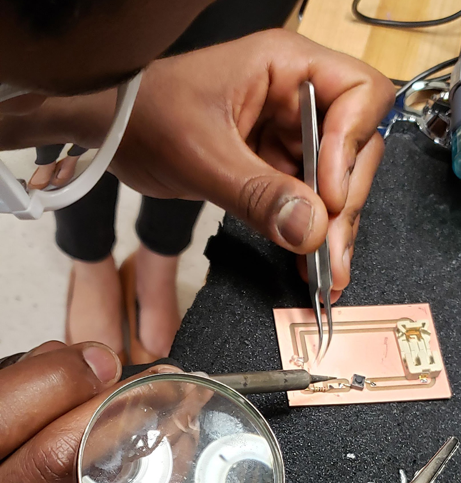 Soldering surface mount components to the PCB board: LED, switch, battery holder. The first three months of 2019 saw a flurry of Professional Development in Fab Labs from Mississippi/Louisiana to California. Fab Labs have a full quiver of digital fabrication tools and a well-stocked electronics station. The goal for these Professional Development workshops or FFI’s (Fab Faculty Institute) was to do some cross-platform training that would introduce faculty and lab managers to equipment and techniques that are often underutilized. While we go into the Fab Labs with an agenda for each day, the most important aspect is for faculty and managers to have time to “mess about” with some guidance from the FFI leaders.
Simple electronics, sewing and embroidery
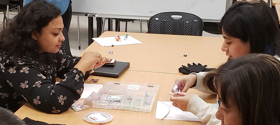
In Santa Clara, middle school and high school teachers expressed an interest in learning about Arduinos so that they could help their students in robotics competitions. Arduino is an “open-source electronic prototyping platform enabling users to create interactive electronic objects.” Instead of using actual physical components such as capacitors and resisters to control inputs and outputs, one can write code and load it onto the Arduino. Rather than leap to Arduino without understanding the basics of circuits and electricity, we started with some simple circuits using conductive thread or copper tape, LEDs, batteries and switches.
 Basic circuits on the board.
 Teachers using popsicle sticks, copper tape, LED’s, batteries and clips to prototype circuits. With help from FFI leaders, one teacher used VCarve Pro to create a drawing for a circuit, machined a copper blank using a 1/16” bit on the ShopBot CNC, and soldered the surface mount components to the PCB to make a flashlight. One project, several skills.
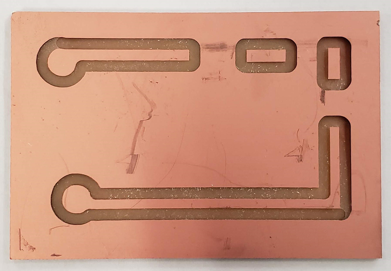 PCB blank with a thin layer of copper on the board, machined on the ShopBot PRTalpha with a 1/16” bit.
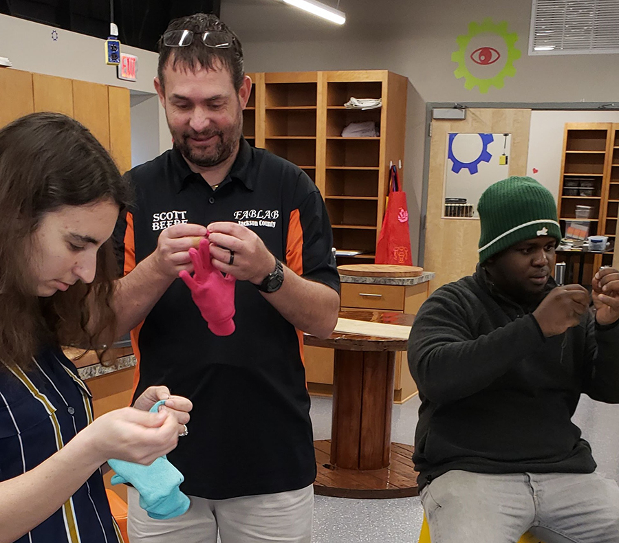
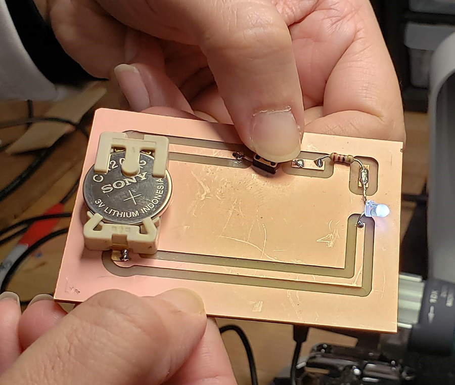 A functioning flashlight. In Jackson County, Mississippi, managers from three Fab Labs joined together: Jackson County (Vancleave, MS), NOLA (New Orleans, LA), and the newest, Jackson (Jackson, MS). They were interested in learning about the sewing/embroidery machines that often sit idle because A) sewing is a skill that is seldom taught in schools or at home B) the digitizing software is unfamiliar to them c) they had never taken the time to actually use the machines.
Again, we started with the basics: hand sewing. In a room of adults, several had never threaded a needle or tied a knot in thread. To make the project a bit more interesting, we used conductive thread to make ordinary gloves into “smart” gloves that could be used with smart phones.
 Hand sewing conductive thread onto the fingertips of gloves.
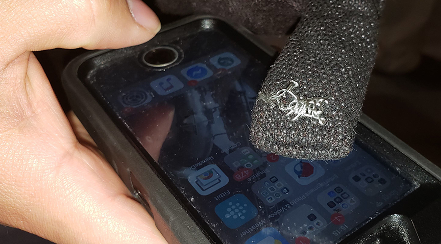
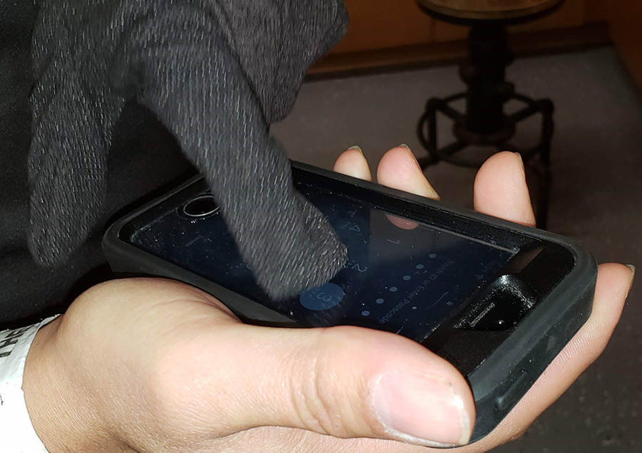 With a simple pad of conductive thread, an ordinary glove now works with a smart phone screen. From there, we threaded the sewing machine and used utility stitches to make a little bag, and the embroidery stitches to personalize it. What does this have to do with ShopBot? The digitizing softwares for embroidery machines are CAD programs. Many of the terms and tools used in one software are the same as the CAD software used for the ShopBot CNC or a laser cutter. Who knows which machine will spark enough of an interest in a teacher or a student to get them over their fear of using a computer-controlled or digital fabrication tool? Success on one digital fabrication tool can open up worlds.
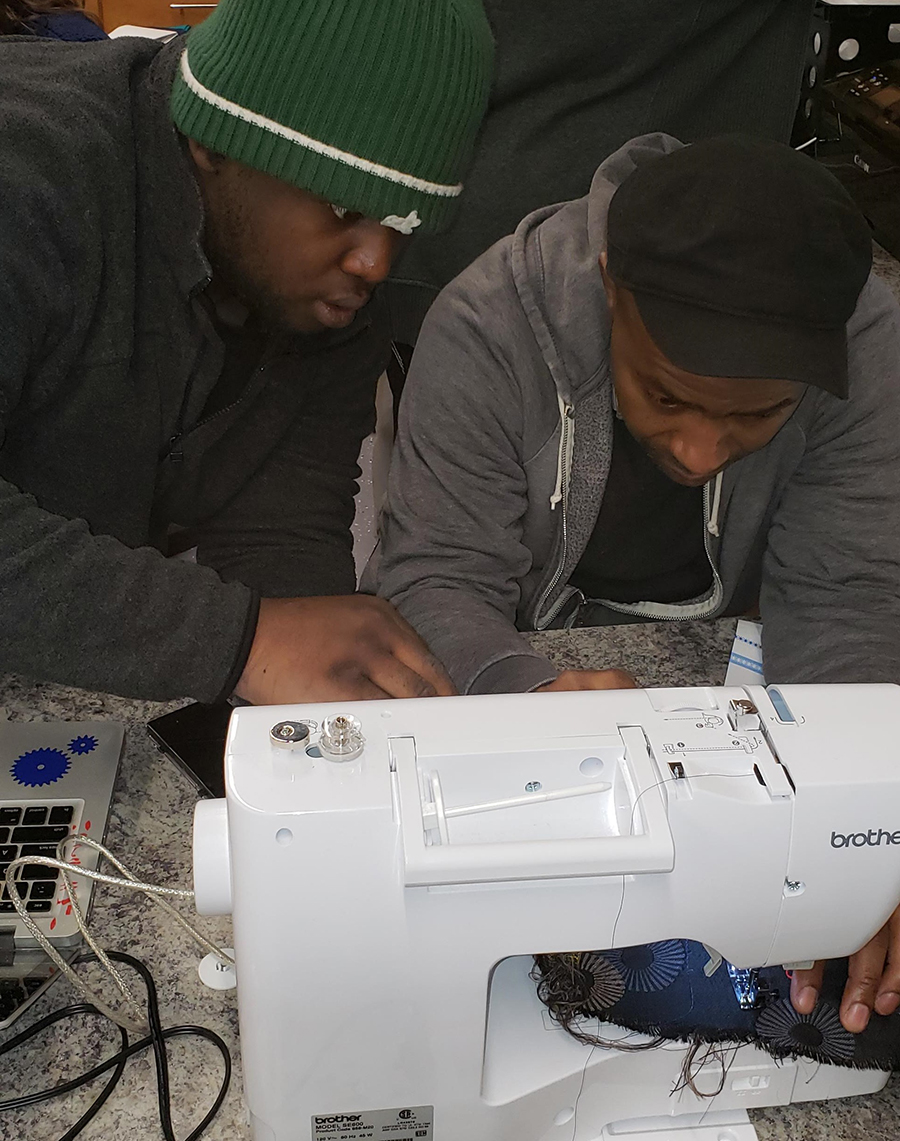 Using utility stitches with a sewing machine.
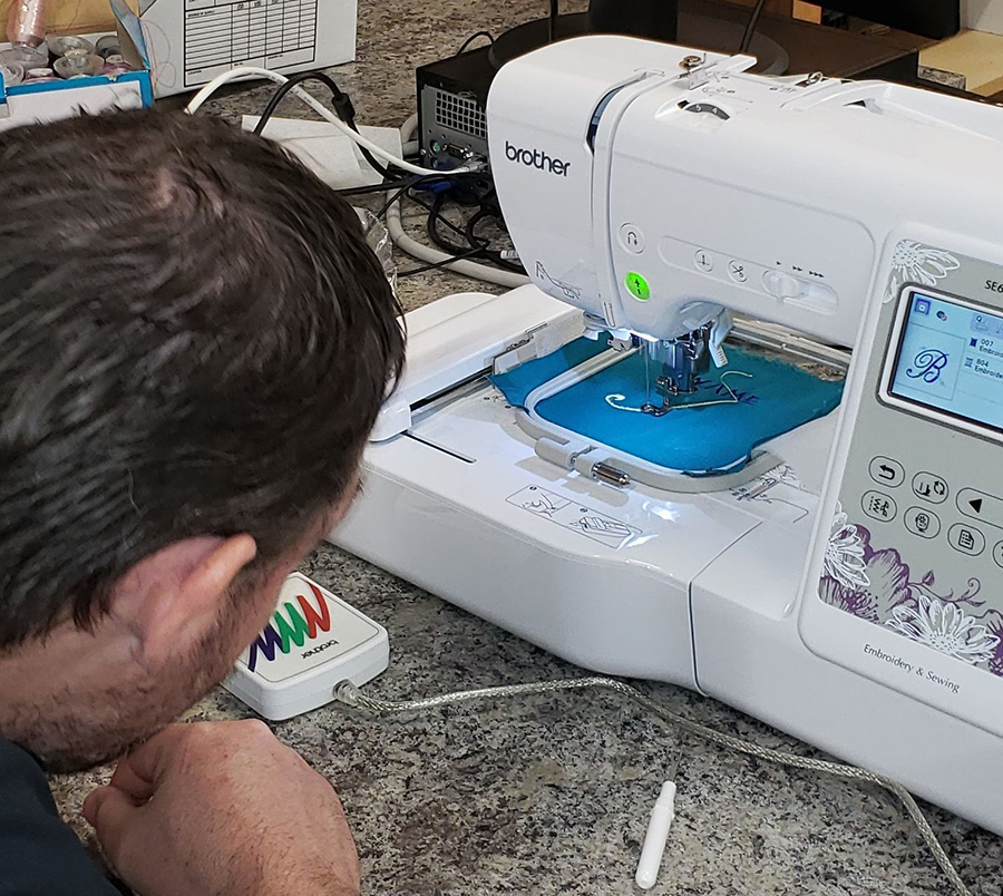 Watching the embroidery machine do its thing.
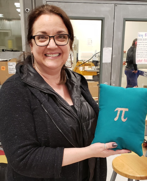 This math teacher from Santa Clara didn’t know she could have an interest in an embroidery machine. Check out that smile after digitizing Pi, embroidering it onto fabric, and sewing up a pillow! 3D Carving, Molding and Casting
3D printing was intended for rapid prototyping of designs, and was not intended for production of multiple copies of the same thing, like rubber duckies or Yoda heads. But its rise in popularity has contributed to the development of many CAD software applications, and even 3D scanners, that can create 3D models on the computer. Many of the same files that can be used with a 3D printer can be 3D carved on a ShopBot, and the resulting model used to create molds to aid in the production of many copies.
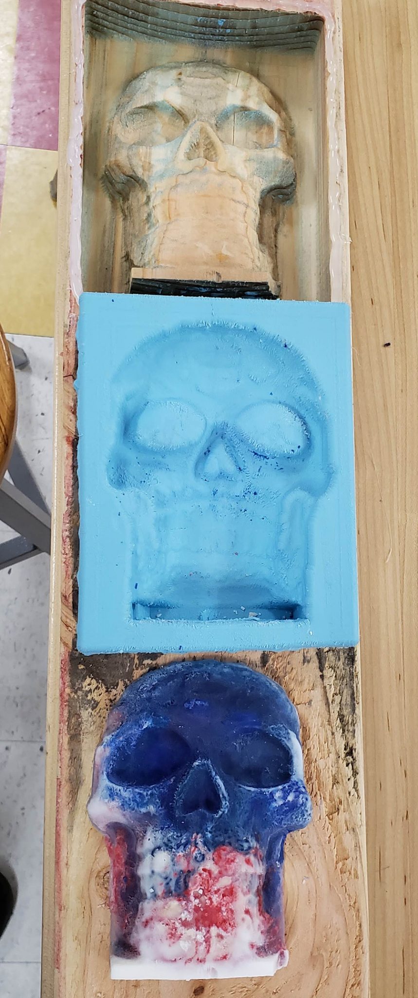
At Santa Clara, we imported an .stl file into VCarve Pro for machining on their ShopBot PRTalpha. After sizing onto a 2”x 6” from the local building supply store, we created a roughing pass to clear out the majority of the material. We then used a ¼” ball nose bit to finish the 3D carving. Time from start to finish for the roughing and finish passes: 27 minutes.
Once we had the model, we added a bit of hot glue around the edge to give the mold a little more depth, then filled the model with a two-part flexible mold making material from Smooth-On. After it cured, we pulled the mold from the model. For this experiment, we filled the mold with melted paraffin and crayons. Think soap, plaster, or, with food-grade mold material, chocolate!
 Model 3D carved on the ShopBot (27 minutes), and mold made from a two-part material from Smooth-On.
 Some of the molding and casting materials available from Smooth-On.
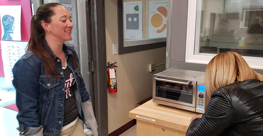 Carefully watching the paraffin and crayons melt in a toaster oven.
 Paraffin and crayons cast in the mold.
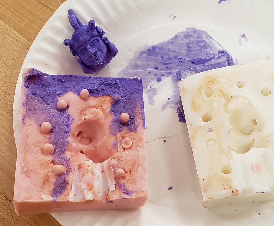 Another object cast in a 2 part mold made from a 3D printed model. Notice the “nobbies” added to align the two sides of the mold, and sprues added to allow the material to be poured into the mold, and air to escape while the material is poured in. ________________________________________________
The leaders of the FFI in Mississippi: Sallye Coyle and Chris Carter
The leaders of the FFI in Santa Clara: Sallye Coyle, Andrea Fields and Chris Carter (www.TIESteach.org)
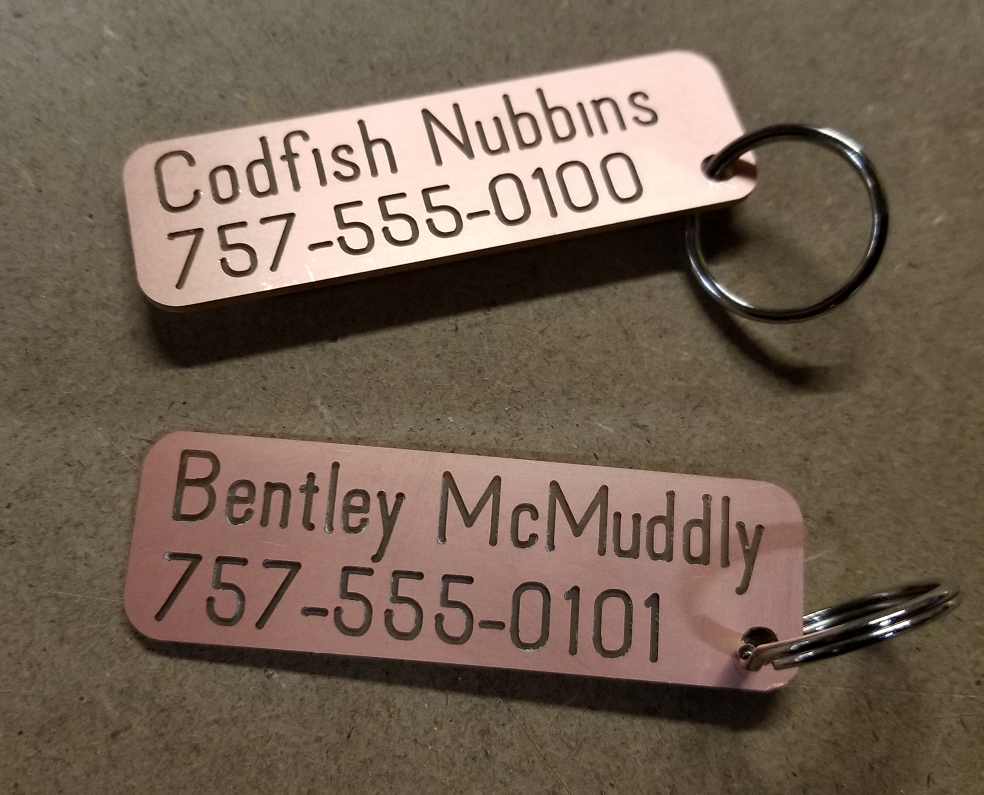
If you’re like me you hate the paper tags that transportation services give you to identify your bags when you travel. Recently I decided to make myself some that were more durable and would look WAY cooler.
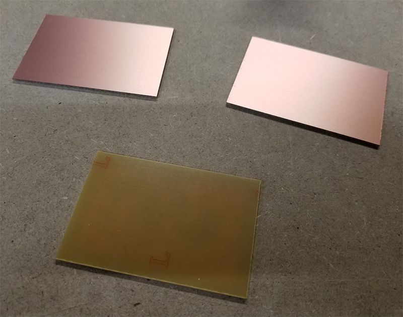
I dug around in the shop and found some machinable circuit board blanks that were left over from a couple of projects. Unlike traditional FR-4 circuit board blanks that are designed for chemical etching and have a fiberglass backing, the machinable FR-1 blanks have a paper and resin backing that is easier on bits… and your lungs! The ones I had were single-sided (with copper on only one side) and were 2” x 3”, but they are available in larger sizes and with copper on both sides.
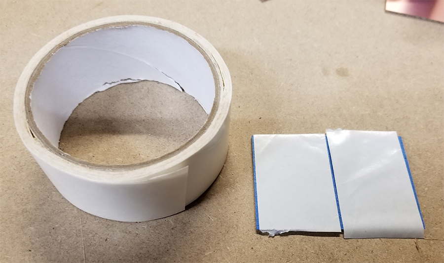
I was going to machine my tags on a Handibot® Smart Power Tool which I had mounted to an mdf baseplate, so my first decision was how to hold the blank securely to the mdf while machining. There are lots of options, but the simplest was to use double-stick tape. It holds well, but can leave some sticky residue on the back of the blank. Fortunately, a layer of masking tape or vinyl applicator’s tape on the back of the blank will peel off cleanly.
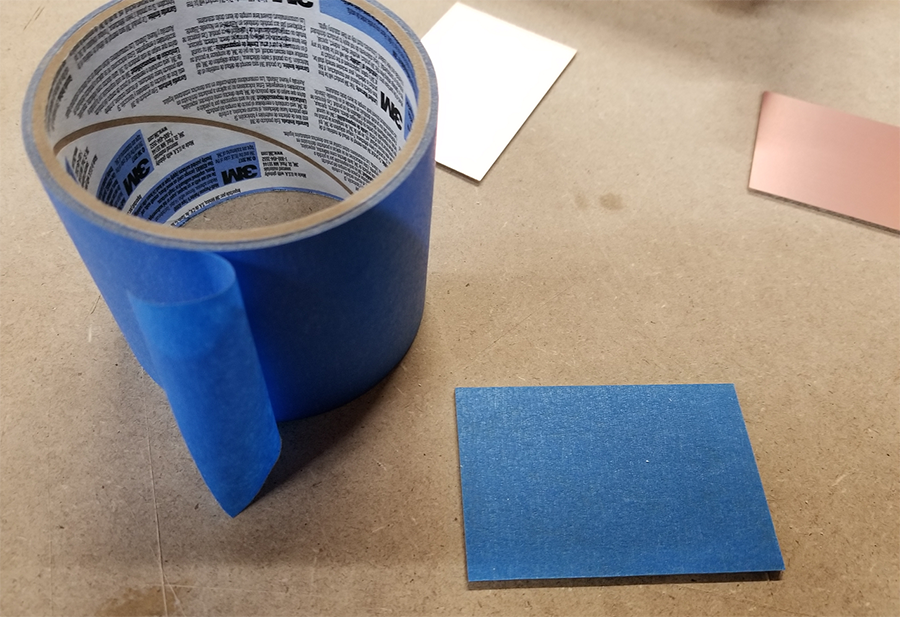
I haven’t had much luck with double-stick Scotch tape so I generally use carpet tape, available at just about any hardware store. Since I want the blank to be flat and secure I covered the whole taped blank with the double-stick, but you can certainly use less if you want.
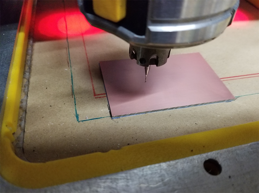
After squeegeeing everything flat, the last prep step is to peel the backing off the double-stick tape and place it in the correct location for machining. I had already made some marks on my machining surface that marked the 0,0 corner, and aligned the blank with those marks and stuck it down securely.
Design Decisions:
I had three decisions to make:
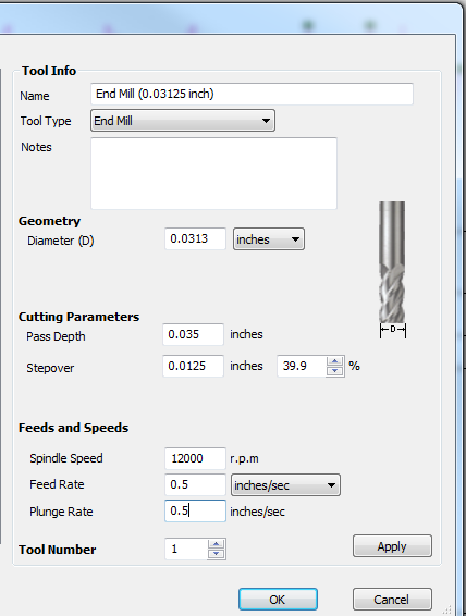
- What size and type bit to use? I knew the bit needed to be pretty small, but wasn’t sure if I wanted to use a V-bit or a straight bit. A V-bit can make nice sharp corners, but the blanks are too thin to use a V-carving toolpath strategy and in a blank this thin, any variation in flatness would be pretty noticeable. I decided on a 1/32” straight bit from Precise Bits with a down-spiral geometry to keep from pulling the copper layer up
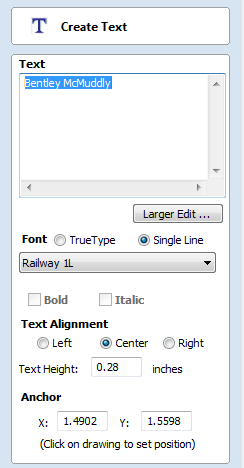
- What font? Since I wasn’t going to be using a v-carving toolpath, a single line font made the most sense—and my go-to single line font in VCarve is Railway 1L
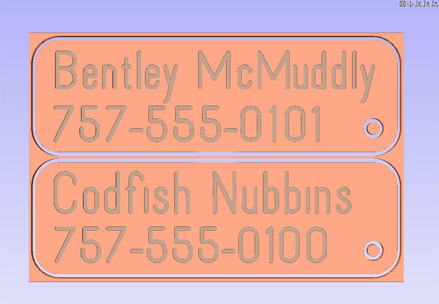
- What shape tag? I wanted to keep it simple and decided on a rectangle with rounded corners and a hole near a corner for a ring. I wanted a couple of tags that would be almost the full size of the blank, but also wanted some with just a name and phone number. With a little fiddling two of those would fit on each blank.
Draw and Toolpath:
I started a new drawing with a 2”x3” workspace that was 0.06” thick, the size of my circuit board blanks. I created two tag blanks with a bit of space between them, drew a corner hole that fit the rings I had, and entered the text for each tag. It took a little fiddling to get the text sized and positioned correctly, but once it was done I created two toolpaths.

The first was the text which I cut 0.02” deep to cut through the copper layer, using a Profile strategy with the On The Line option. To cut the tags and holes I also used a profile strategy, this time with the Outside option. VCarve is smart enough to understand when something is “Inside” something else, so the hole was cut on its inside while the tag was cut on the outside. To make it easier on my tiny 1/32” bit this cutout was done it 2 passes, using a spiral plunge to ease into the cut and minimize the load on the bit.
The preview looked good so it was time to cut!
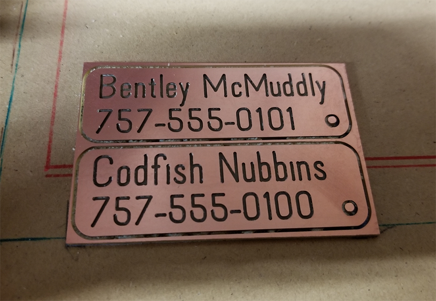
When the cutting was finished I popped them loose from the mdf and was really happy with how they turned out. The cuts turned out really smooth, with just a quick pass with some 220 grit sandpaper to ease any sharp edges just a bit.
Supplies:
I get the circuit board blanks from Inventables, but they are available from lots of places these days (even Amazon). Just make sure that you get FR-1 blanks that are made for machining.
There are many places to get small bits, but my go-to place is Precise Bits. They have a large selection of bits and collets, but I’ve also heard good things about Driilman1 on eBay.
|
|


... Learn to use a CNC")


