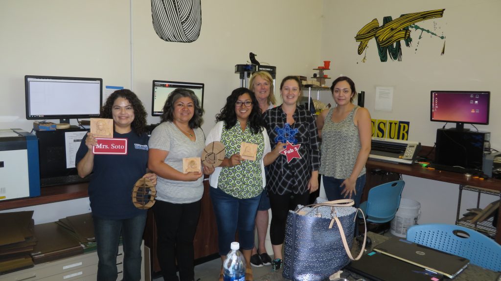
On a recent Professional Development session (PD) at the Chevron FabLab at California State University Bakersfield, Caroline McEnnis and Sallye Coyle of TIES (www.TIESTEACH.org) spent three days working with teachers, interns and staff to give them more experience with the digital fabrication tools and electronic components available in their Lab. Caroline had the attendees use a Kinects to scan themselves in 3D, then had the 3D printers print out tiny plastic versions of the scans. Later, Sallye showed the teachers how they could do more than print their 3D file (.stl) on a 3D printer. She had the teachers bring the models through VCarve Pro to create files that could be machined in wood on a ShopBot CNC.
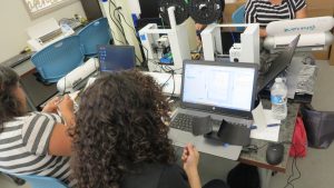
3D printers printing heads scanned with a Kinect while teachers work on another project
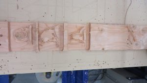
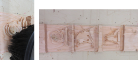
Three of the scanned faces on a 2 x 6 board after running the roughing phases
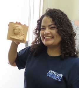
Finished model with the original. Resolution was determined by the resolution of the scan, how the .stl was scaled from the original, and the size of the bit to carve the file (.25″ ball nose).
This is not a full tutorial, but an example of the steps we went through to machine the images in 2″ x 6″ boards. What could a teacher do with this? How about creating a totem pole with each student’s image as a class project? What can one teach about history and culture by studying totem poles? Are the more important images placed at the top of the totem pole, or at the bottom?
Steps:
- Create the scan: The Internet has information on how to connect a Kinect to a PC to create a 3D scan. Here is one option. Virtually any 3D scan that creates an .stl would be appropriate.
- Bring the .stl into VCarve or Aspire (NOTE: version of VCarve Pro must be 7.5 or later):
- The HELP file in VCarve and Aspire is excellent; please refer to it in detail. The HELP is bookmarked, so when you click on the item you are interested in, it will go to that page.
- By clicking on the MODELING tab at the bottom of the left hand screen, you will see the options for working with a 3D model or component such as an .stl.
- When you import a component, you can choose what orientation to import the data. Keep clicking until you have the front view of the scan face up in the material.
- Change the view to the side view, and slide the bar until you have most of the image that can be machined from the top down (no undercuts). Delete the data below zero if you are only going to machine the face. If you want to do 2-sided carving, create both sides then separate the two 3D components for machining separately.
- You can only import one .stl at a time into VCarve Pro, so you may have to open a separate session of VCarve Pro for each face. As long as you know where to place them on the board, you can then machine them as needed (try putting a rectangle where each of the faces would go. You can then copy a vector or component from one session of VCarve/Aspire, then paste it into the same location on another session).
- The HELP file in VCarve and Aspire is excellent; please refer to it in detail. The HELP is bookmarked, so when you click on the item you are interested in, it will go to that page.
- Lay out the components on the virtual board, then toolpath them
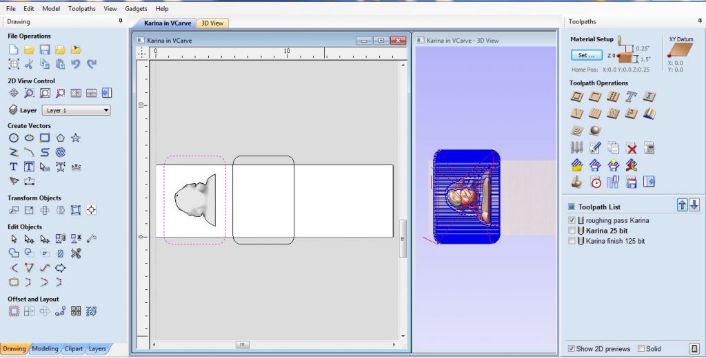
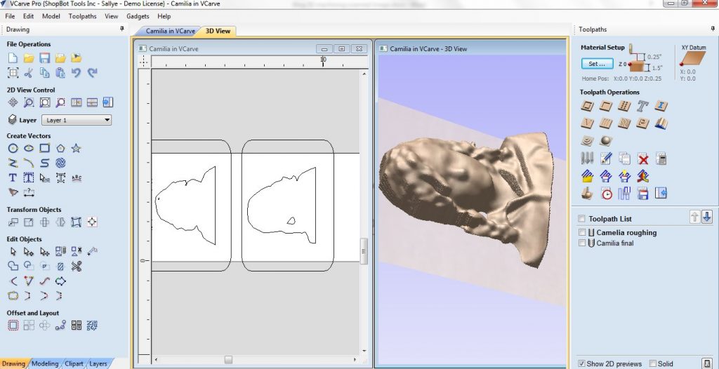
- In the image below, the first of three 3D components laid out on the virtual representation of the board measured 24″ in the X (arbitrary length) x 5.5″ in the Y x 1.5″ in the Z (standard measurements of a 2″ x 6″), with the Z zero set to the top of the material. The component was placed in the center of a rectangle that was placed on the board. A second rectangle was also placed on the board to mark the location of a second 3D component.
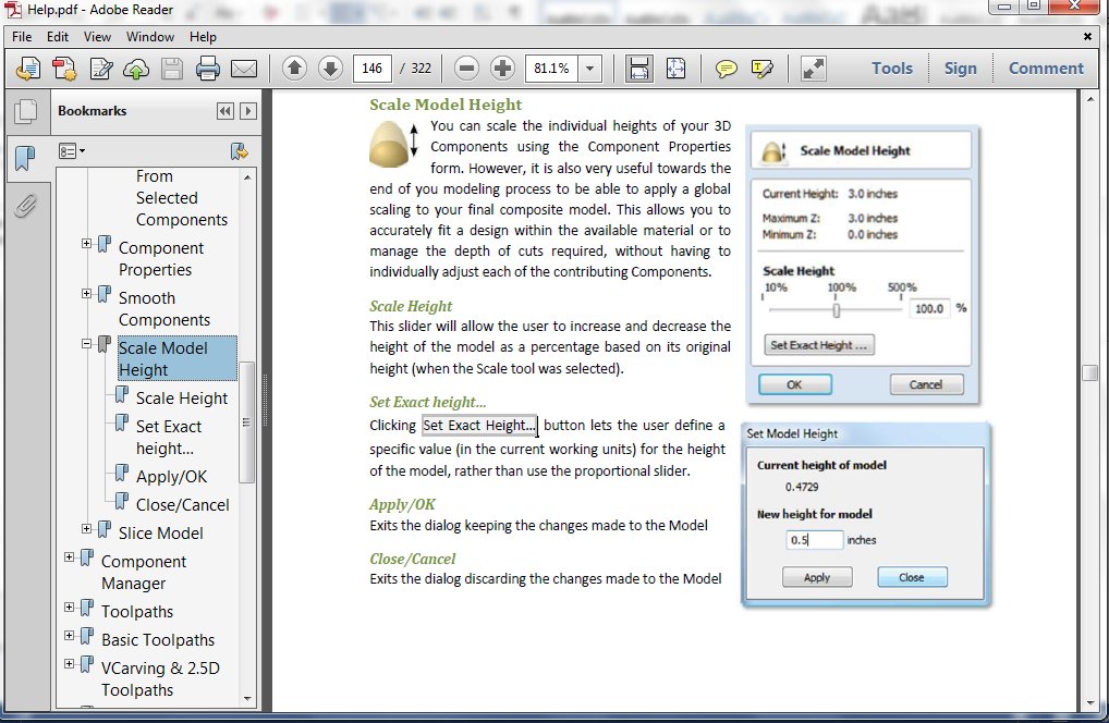
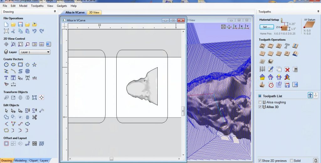
- The height of the model was reduced to fit onto the thickness of the board. A model that has been flattened so that it keeps the features of the full 3D but would not be as thick as the original when viewed from the side is called bas (pronounced “baa”, French for “low”) relief.
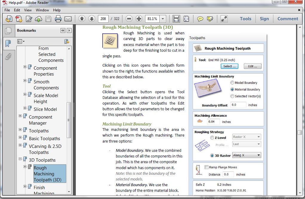
- Select the rectangle surrounding the component and set the roughing pass. In this case, a .25″ end mill bit was used for the roughing passes.
 The screen below shows both 2D and 3D views. The 2D (left view) shows the placement of the component surrounded by a rectangular vector. The 3D (right view) shows the 3D rendering of the component with the roughing passes overlaid. The CAD menu screen (left side) and CAM menu side (right) are also shown. The 3D toolpathing options are circled.
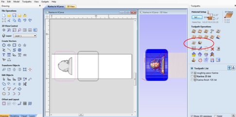 In this first sample for the 3D finish pass, two bit options were tested (virtually). While the .125″ ball nose bit would give more detail, it would take more time to machine than would the .25″ ball nose bit.
- Create two toolpaths, one for each bit. The use the icon that looks like a clock to see the estimated time for each of the toolpath options.
- Use the Preview icon to look at each of the toolpaths. Remember to reset the preview in between testing the toolpaths. This particular model does not really need the detail from a .125″ bit.
- In the image below, the first of three 3D components laid out on the virtual representation of the board measured 24″ in the X (arbitrary length) x 5.5″ in the Y x 1.5″ in the Z (standard measurements of a 2″ x 6″), with the Z zero set to the top of the material. The component was placed in the center of a rectangle that was placed on the board. A second rectangle was also placed on the board to mark the location of a second 3D component.
- Save the roughing and finish toolpaths (use the “floppy disk” icon)
- Save the roughing pass separately from the finish pass.
- Give each toolpath a name that you can remember later (you might include name of person scanned, roughing or finish pass, type of bit used, etc.).
- Do the same for each of the other faces
- Prepare the board for machining on the ShopBot
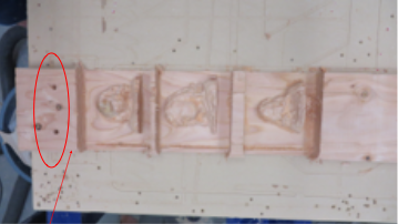
- Photo below shows board after faces completed how the hold down was placed outside the area of travel for the machining.
- The board was placed on the table so that the bit would not go outside the range of travel in the Y-axis (board moved away from the long edge of the table).
- Holes for screws to hold down the board were drilled before sheet rock screws were screwed through the board down to the sacrificial board under the 2 x 6. The length of the design area was measured (24″), and the screws placed outside that design area. See red oval for placement of screws at the top of the board.
- The X and Y axes were zeroed at the point where the first face would be machined to further ensure that the bit would not hit a screw while machining the file. Arrow points to where bit was positioned at place where file would start, then the Z2 command (or button on keypad screen) used to set that location as X and Y zero (0,0).
- Run all three roughing passes
- Run each of the ShopBot (.sbp) files that use the .25″ inch endmill to rough out the faces, one after the other
- Run each of the ShopBot (.sbp) files that use the .25″ inch endmill to rough out the faces, one after the other
- Change the bit to the .25″ ball nose bit and do the finish passes, one after the other
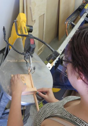
- If necessary, use the scroll saw with a blade (or the band saw) to cut the faces into separate blocks
Other options for using 3D models:
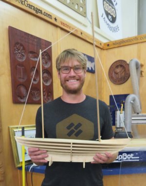
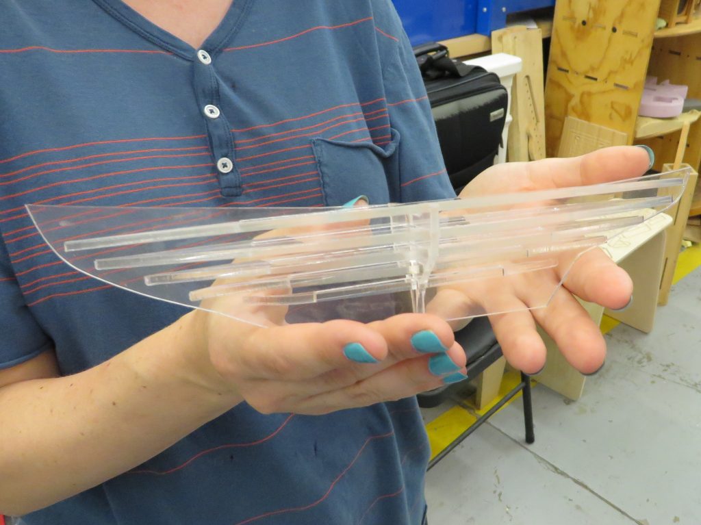
- Take the file through 123Make to turn a 3D model into 2D build plans. Photos below show a 3D model of a boat “sliced” and machined in wood on a ShopBot and in acrylic with an Epilog laser cutter:
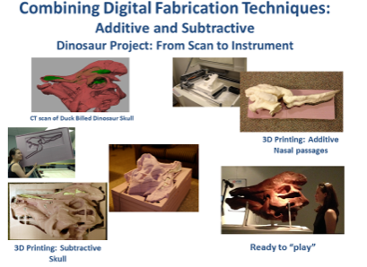
- In the example below, a CT scan of a duckbill dinosaur skull was taken through Rhino, then Aspire CAD/CAM software and “sliced” into 2″ thick panels of pink insulation foam which were machined on both sides. The sinuses and larynx were printed on the 3D printer, the whole thing reassembled, and a Ph.D. student used it in her dissertation: