Fusion 360, a powerful cloud-based CAD/CAM software that is free for educators, has been gaining popularity in schools because the design files can be output to multiple digital fabrication tools such as CNC machines (like ShopBot tools), laser cutters, and 3D printers. While the price is right, sorting through the possibilities and keeping track of the design flow can be daunting for both new and experienced users of CAD/CAM software and ShopBot CNC machines. With this in mind, ShopBot’s July session of the Digital Fabrication for Educators workshop, led by Sallye Coyle and David Bryan, worked through Fusion 360 with a group of willing and patient educators.
There was a 3D printer and a laser cutter present at the workshop, but a big part of the event was for everyone to get hands on experience with setting up a CNC for machining. Whether new to the process, or with a couple of (months/years) under their belt, everyone went home with new tips and tricks for CNC use (and VCarve Pro).
Getting Started: A “Simple” Open-Faced Cube
Fusion 360 is an engineering-based 3D rendering program. Translation: Start with a 2D drawing or “sketch” on a plane or face (X, Y, or Z axis), then extrude it into a 3D rendering or “body” that can be viewed and manipulated from multiple angles on screen. Many tools in the drop-down menus (Sketch, Create, Modify) allow the user to create and manipulate models.
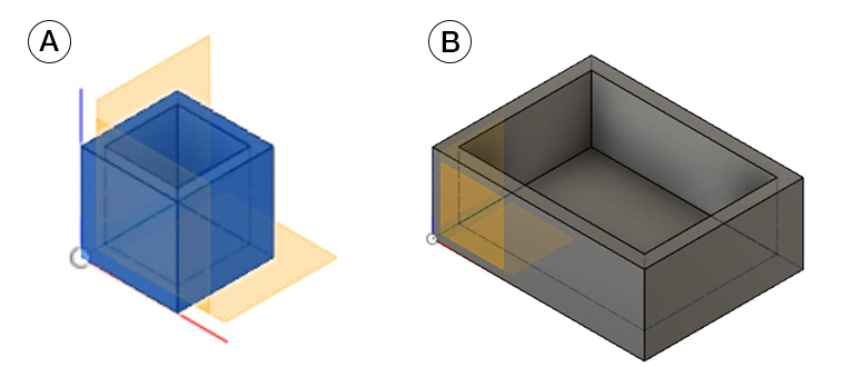
To create a 1” cube with an open face, one could start with drawing a rectangle with fixed dimensions in two axes (X and Y: Sketch menu). Then, extrude the cube into the Z dimension one inch (Create menu). Using the “shell” tool under the Modify menu, make the solid cube into an open-faced cube with walls that are .125” thick.
![]()
The resulting 3D model can be exported as an .stl for 3D printing or 3D carving on a ShopBot or other CNC machine. Alternatively, the 2D sketch (X and Y) of the top face with the outside and inside edge of the cube could be exported as a .dxf for use with the ShopBot. In that case, the Z dimension would be created in the toolpath option (profile or pocket) rather than taken from the 3D body itself.
3D printer starting on the 2+ hour print of the 1” cube.
Parametrics
A power of Fusion 360 is that it is parametric. Translation: instead of being dependent upon a fixed value for a dimension or parameter, one can create a “User Parameter” for the dimension. If the value of the User Parameter changes, the entire model will change accordingly. Table 1 (below) shows the original dimensions set for creating a 1” cube (bottom), and a set of User Parameters defined for the Width_X, Depth_Y, Height_Z and Wall Thickness of the cube (top.) Table 2 (below) shows how the model changes when the original dimensions are replaced with the User Parameters. It makes updating the model extremely easy. Think of building slotted furniture and being able to change the slot size (and cut depth) to reflect the actual thickness of the plywood by simply by changing the value of the User Parameter.
Table 1: Fixed Model Parameters defined in initial cube. User parameters are defined for future use.
Table 2: Fixed parameters replaced with User Parameters. Note Expression and Value changed from Table 1.
A) 1” cube with Fixed Parameters B) Cube resized with User Parameters
The samples above are made with a single “component” (open faced cube.) The sizes are manipulated by changing the values of the “User Parameters.” Objects in blue or grey filament are 3D printed. (Time to 3D print the 1” cube at high quality: 2Hr 20 min.) Models in wood were machined on a ShopBot Buddy® from a 2” x 6” board, using the CAM features of VCarve Pro. [Time to hollow out both cubes from either 3D .stl (roughing and finish pass toolpaths) or 2D .dxf (pocket toolpath) and cut out the cubes (profile toolpath): 10 – 15 minutes total, both cubes.] Fillets in the corners can be added in the Sketch mode, the Create mode, or are a result of machining inside corners with a round, rotating bit.
Preparing 3D models for 2D laser cutting or CNC machining
Fusion isn’t just for 3D printing (additive) or 3D carving (subtractive) of models. It is also very useful for creating and inspecting the model in its 3D rendering, then preparing the various faces for 2D cutting of sheet good materials.
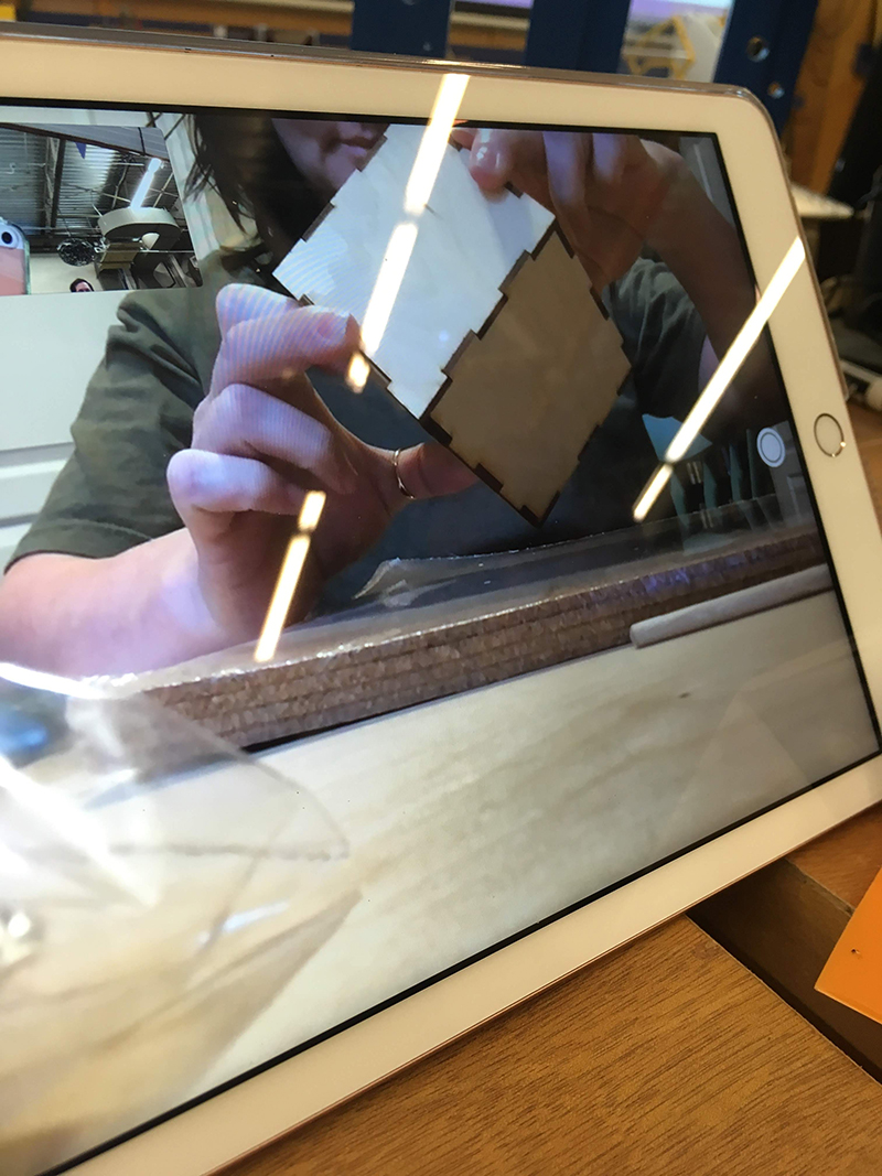
In the photo above, a finger-joint box is rendered in 3D, then the 2D sketches of each face have been exported for cutting out of cardboard on the laser cutter. The white and blue cube was machined out of ¼” King Color Core HDPE on a ShopBot. User Parameters were used to change the size of the models.
In the files created for the ShopBot, “dogbones” were added to the internal corners to account for the fact the closest a rotating round bit can get into an internal corner is the radius of the bit. Adding a bit more space to the internal corner means a square corner can fit into the finger joint. An add-in developed by Brian Ekins makes adding the dogbone to a Fusion 360 model as easy as clicking on the model and defining the diameter of the bit.
Adding “Components” in a Fusion Model
The first example of an open-faced cube for 3D printing or CNC machining out of a block of material is relatively simple because there is basically one part in the model. In contrast, a finger-joint box that is cut out of sheet goods is made up of several different sides. In the photo below, the open faced box has 5 different pieces: a top, a front, a back, and 2 sides. The design must take into account that the joints on the edges are not all the same because each face must fit into its corresponding joints. Top and bottom (if there was one) would be the same, Left and right have the same joints, but are mirrored from each other if the inside and outside are not interchangeable. Likewise, the front and the back have the same joints, but are mirrored from each other.
One way to keep track of the different parts is to separate them into different components. The term “component” has different meanings in different software, but for Fusion, it’s easiest to think of a component as a “level.” A component can have, within it, Sketches, Bodies and CAM set ups. It can be turned on and off to make it easier to see what one is doing. Fusion treats a “Body” differently than a Component. However, one has the ability to convert a Body into a Component to help keep track of the various parts and pieces. Yes, it is a lot to process.
Examine each side of the above model. The joints on the edges are different for each piece, though the sides and front/back are mirrors of each other.
Once a 2D .dxf file has been created from the 3D rendering, it can be sent to a laser cutter remotely. Heather (visiting ShopBot in Durham, NC) sent the finger joint box file to her sister in Utah, who cut it with a GlowForge laser cutter.
CAM with Fusion 360
One big difference between Vectric software (like VCarve Pro) and Fusion 360 is in setting up for the CAM (manufacturing) with a CNC machine like a ShopBot. The first question that Vectric software asks when one opens a new CAD file is “what is the size of the material,” as well as the origin of the X and Y axes and the Z axis origin. That information is carried throughout the entire design and toolpathing (CAM) options. In 2D toolpathing (profile, pocket, drill) the Z or cut depth is defined by the user. In 3D toolpaths, the Z or cut depth is defined by the 3D model.
Chris came into the class with more experience in the CAD side of Fusion 360, and used the workshop to get more familiar with the CAM side. He imported the “Georgia” as a bitmap into Fusion 360, then drew the vectors. He discovered that it might be more efficient to trace a bitmap in another software rather than hand following in Fusion 360.
In Fusion 360, one does not define the material, the origins, or how the parts fit onto the material until all the components have been designed. In its default mode, the Y axis is up, so one has to define Z as up in preferences. For the most part, Z depth is defined by the model. Paying attention to where the software is defining the start point of the model is critical. Preview the toolpath before writing the ShopBot code, read the code, and do an air-cut to avoid mistakes. And do make sure that the Z axis on the ShopBot is set up the same way as it is in the code so that the bit doesn’t plunge too deep into the material, or ride above the material, when actually running the file.
David and Sasha chose to celebrate their 23rd Anniversary by attending the class. David works with robotics students, and prefers Fusion 360 as the design software because of its engineering base and parametric qualities. He wanted more hands-on time with the ShopBot. Sasha is principal of an elementary school, and wanted to learn more about digital fabrication in general. Yes, this was a class with an emphasis on Fusion 360, but they ended up creating their final sign in VCarve Pro. It wasn’t until they were showing off their sign to their sons that they discovered their mistake. The design and toolpathing is perfect. However, the month was July =)
__________________________________________
A note about the workshop leaders
Sallye is fluent in Vectric software (VCarve Pro, Aspire), which is more graphic-based (think artists and signmakers) and, to her mind, more intuitive for beginners. While there are always tricks to be learned/taught, the basic workflow of CAD (what and where), to CAM (how), to creating files for the ShopBot, can be demonstrated fairly quickly in the Vectric software. For Sallye, working in Fusion 360 has been like learning Russian when her first language is Spanish: she can now maybe order a meal, or go grocery shopping, but actually having a conversation that includes jokes or writing a short story will require more practice and tutorials. Thank goodness for YouTube videos, especially Lars Christensen, Taylor Stein and Jim Yost. She pays attention to the little asides that experienced users assume that newbies will know. Sallye is looking forward to getting more CAM tips at the upcoming Fusion Academy in Portland to expand her knowledge of Fusion 360 for 3, 4, and 5 axis machining.
David has a background in Solidworks and Rhino, engineering-based 3D rendering programs. So Fusion0 360 is not quite as great a leap. He is also more fluent in 5 axis machining, since he has been working with the ShopBot 5-axis tools.
A big thank you to the patience and sense of humor of the first group to attend a Fusion 360 training while Sallye and David worked through what can be accomplished in a 2 + day workshop. We learned a lot! Let us know if you’re ready for another Fusion 360 workshop at ShopBot.
Leave a Reply