This blog post originally appeared on the 100k Garages blog in 2017. I often get requests for information regarding two-sided machining on a ShopBot tool and figured with that many people asking about it, that we should cross-post it here on the ShopBot blog for additional accessibility. I have edited a few things to account for updates in later versions of the Vectric software.
_______________________________________________
A good friend recently sent me a Solidworks file, and asked about machining it on a ShopBot. I don’t have Solidworks on my computer, so I requested and received the model as an “.stl” file. The model could have just as easily been created in Inventor, Rhino, Fusion 360, or any other 3D rendering software/scanner.
Since I do have Aspire CAD/CAM software (VCarve Pro’s big sister software), I imported the .stl (component or 3D model) twice (inside and outside) so I could plan my strategy. I originally wrote this blog using VCarve Pro v. 8.0, which was fully capable of doing all the machining. Vectric software v. 9 and above give you the option of setting up a two-sided file, so that would eliminate some of the steps outlined below. One caution: With VCarve Pro, you can only import one component at a time. That would work for this application, since the “Inside” and “Outside” of this project need to be treated as separate CAD/CAM files.
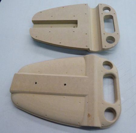
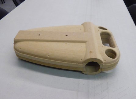
The photo below shows the finished result. At the end of this entry, I have indicated how I would charge for a project such as this.
Steps to Examine the Model
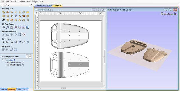
- Use the tools under the Modeling tab to import the 3D model into the Vectric software.
- If using Aspire, import the .stl twice, once for the “Inside” and once for the “Outside.” If using VCarve, open up two sessions to import each side one at a time.
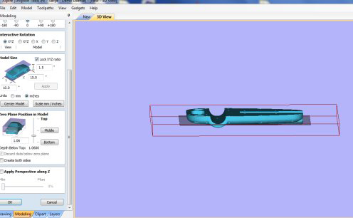
- Use the “slider bar” on the import page to determine where to slice each model to get all the details on each side.
- The total thickness of the model is 1.5″ but each side needs to be machined to a depth of 1.1″. Since the midpoint of the material is only .75″ and each side goes deeper than that, it is best to treat the two sides as two different models.
- See HELP in Aspire/VCarve for terrific instructions on how to do this (this blog entry also gives a few more details).
Givens:
- The project was going to require two-sided machining.
- Two samples were needed to complete the large seat bracket (~15″ tall and 1.5″ thick per sample).
- The customer didn’t specify any requirement for material.
- The material needed to be exactly 1.5″ thick so that the inside and the outside of the sample would line up correctly.
Thinking Through the Project
- Gluing up two pieces of 24″ x 24″ x .75″ MDF would:
- Fit two completed samples onto the material.
- Be a more consistent thickness than plywood.
- Fit on a number of different sized ShopBots (Desktop MAX, Buddy, Gantry).
- Letting the store cut a 2′ x 4′ x .75″ piece of MDF in half crosswise would save having to do it at home.
- Gluing the two pieces together with wood glue and letting them dry would make up a board 1.5″ thick.
- Purchasing a dowel at the same time would help with the registration of the board for flipping.
Setting Up the File and Materials for Two-sided Machining
- Set X, Y origin in the CAD file to the middle of the material.
- Set Z Zero to the top of the material.
- Decide how to flip the material (horizontal or vertical).
- Use 4 dowels as registration markers.
- Start with a temporary spoil board attached to the table, and machine the dowel holes and center point into the temporary spoil board.
- Indicate in the CAD file where to put hold down screws in the temporary spoil board, and in the actual material.
- Attach the actual material to the temporary spoil board, then machine the center point and dowel holes into side one.
Prepping for “Inside” Machining (File #2)
Analyzing the file, observe that some sections need to be created as a 3D (simultaneously moving 3 axes) file. However, much of this side can be machined with 2D toolpaths (plunge the Z and then machine at that depth), which will save time and give better results.
- The rounded slot needs to be a 3D file, machined with a ball nose bit.
- The center pocket has sharp inner edges, so should be pocketed with an end mill.
- There are marks to indicate where to use a small drill bit to drill after machining.
- The model can be partially cut out from this side.**
- There are registration guidelines that need to be generated.
- Holes that allow dowels to fit.
- Hold down for base board and material.
The Big Picture
- In Aspire, under Model > Scale Model Z Height, observe that the deepest cut on this side will be 1.1”.
- The material is 1.5” thick, so cutting more than .75” will go more than halfway through the material.
- Note: If the vectors are available from the original file, import them at the same time and overlay them on the 3D model.
- If only 3D data is available, create a vector boundary (modeling tab) around the entire component to define the edge of the model.
- Add some vectors (drawing tab) over the model to indicate where to use pocket, profile, and drill toolpaths.
- Create a second Copy and Mirror the model and vectors, and Center both of them in the material.
- Add registration and hold down vectors, and center them in the material.
Creating Toolpaths for “Inside”
3D Toolpaths
Open the Tool Database (Library) and, if necessary, create two .25” ball nose bits. Start with any ball nose bit, Copy it, and change the name and specifics of the new bit to reflect its use:
- For the roughing bit, set pass depth to .25”; stepover to 40%; and feed rate to 4 and 1 ips.*
- For the finish pass bit, set stepover to 8 – 10%: and feed rate to 6 and 6 ips.*
- Use the roughing bit to create a roughing pass to clear away most of the material by stepping down in .25” increments.
- Use the finishing bit to create a finish pass to result in a smooth, rounded channel.
*These values are good for the gantry tools (wood).
- For Desktop tools, try 3 and 1 ips for the roughing pass and 4 and 4 for the finish pass.
- For a Handibot, try 2 and 1 ips for roughing, with a pass depth of .2, and 3 and 3 for the finish pass.
2D Toolpaths

Specify a .25” end mill bit:
- Pocket to a depth of .84” the flat channel (depth determined in 3D model).
- Profile to the inside the through holes (.75” deep or halfway through).
- Drill the underside holes to a depth of .1” (just as a marker).
- Profile to the outside edge of the model (.75” deep).**
Registration Holes and Hold Down
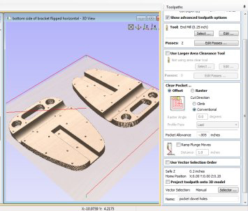
- The dowel measured .5” in diameter.
- Use the Pocket Toolpath option to create a depth that would fit the dowels.
- The registration hole for the dowel should secure the material in the correct location for flipping yet leave some leeway (allowance) to easily get the dowel in and out of the hole.
- To see the Pocket Allowance option, make sure that Show advanced toolpath options is checked.
- A negative allowance makes the hole bigger.
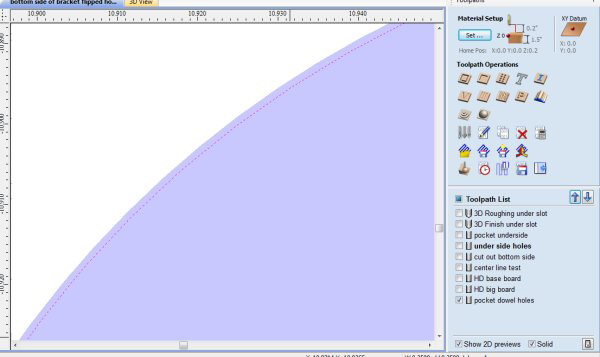
- After calculating and closing the toolpath, ensure that the allowance has made the hole larger rather than smaller. Checking the Solid option at the bottom of the toolpaths screen (or the wireframe/solid at top of page in v.9.5) shows what the bit will actually remove. Zoom in on a dowel hole to see that the bit is traveling slightly outside the drawn vector.
- Hold down markers are created using the Drill routine to a shallow depth.
- These toolpaths are used on the temporary spoil board, and on the first side of the material.
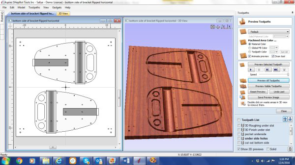
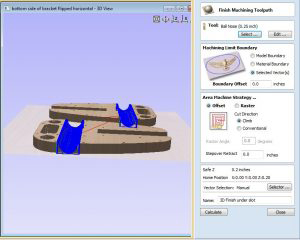
Simulation of the “Inside.”
Prepping for “Outside” Machining (File #3)

Most of this side needs to be treated as a 3D (simultaneously moving 3 axes) file. Only the final cut out will be a 2D profile-to-the-outside.
- Since the bit is a rather large ball nose bit (.25” diameter), one could probably get away with not making a roughing pass. But, there is a rather deep section in the “Outside” holes, so it is better to be cautious.
- Set the finish pass to run very quickly, since it is only taking off a bit at a time.
- The final cut will be to separate the model from the substrate, using a 2D profile-to-the-outside toolpath.
The Big Picture
- First thing is to prepare to line up the ”Inside” and “Outside” models with each other.
- Copy the vector information on placement and hold down from the “Inside” CAD/CAM file, and Paste it into the new “Outside” CAD/CAM file.
- Mirror the vectors, and note how they were mirrored to know how to flip the board.
- Import the “Outside” 3D component and locate it into the vectors. In Aspire, under Model > Scale Model Z Height, one can see that the deepest cut on this side will be 1.02”.
- The material is 1.5” thick. Be aware of how deep the toolpath goes when 3D machining the second side so that the model is not separated from its substrate.
- Offset to the inside of the vector around the entire model to define the edge of the model for the first 3D milling.
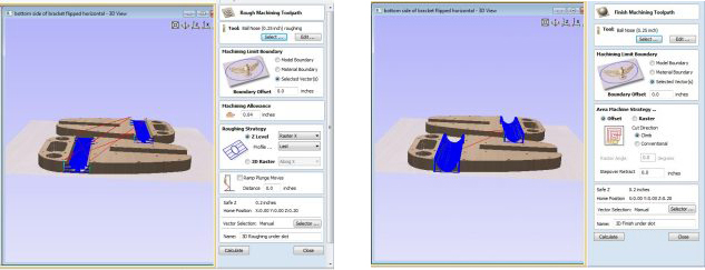
3D Toolpaths

Specifying a .25” ball nose bit:
- Create a roughing pass to clear away the material in the deeper areas.
- To avoid breaking through the material, use the inside (offset) vector to define the scope of the finish pass.
- To finish off the 3D rounding of the edges of the “Outside” side, create another 3D toolpath that runs between the inside offset vector and vector at the edge of the model.
- Cut the parts loose with a final 2D profile-to-the-outside toolpath set to slightly more than halfway through the material.
ShopBot Set Up
- If necessary, surface the spoil board to ensure that it is flat under the material.
- Use the automatic XY Zero routine (icon or C3) to zero the X and Y at the lower left hand corner of the table.***
- Use M2, 12, 12 to move the bit to the center of the 24” x 24” material.
- Zero the X and Y there (Z2).
- Insert the .25” end mill bit into the spindle/router collet.
- Place the temporary spoil board in location.
- Use the Z-Zero Plate to zero the Z to the top of the temporary spoil board.
- Run the ShopBot part file (.sbp) file to mark the location of the hold down screws.
- Screw down the temporary spoil board.
- Look to be sure the temporary spoil board is flat against the ShopBot spoil board.
- Re-zero the Z at the top of the temporary spoil board.
- Run the .sbp file to indicate the center of the spoil board.
- Run the .sbp file to create a pocket for the dowels.
- Test that the dowels slide into the holes easily.
- If the dowels are tight in the hole, rewrite the file to make the hole slightly bigger.
Place the Real Board into Position
- Zero the Z to the top of the real material.
- Run the .sbp file to locate the hold down for the material.
- Screw down the board and check that it is flat against the temporary spoil board.
- Rerun the Z Zero file to the top of the real material.
- Run the .sbp file to create a pocket for the registration dowels. You may have to make them deeper than you did for the temporary spoil board.
- Test that the dowel will fit in its hole easily.
- Note: Dowels themselves should be long enough to jut into the board when it is flipped, and short enough to let the flipped board sit flush against the temporary spoil board.
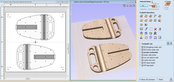
Running the Files
- When machining the first side (“Inside” in this example), the hold downs outside the model should be sufficient for all the work.
- Remember to zero the Z whenever a bit change is made.
- When machining the second side (“Outside” in this example), there will come a point when the hold downs outside the model will not be sufficient to keep the model in place.
- To secure the model for the final machining, AFTER the first 3D finish pass is complete, secure the model to the temporary spoil board using long screws through the two holes in the “Outside” of the model.
Results
These parts were machined on a ShopBot Buddy® (32″ x 24″ cutting area).
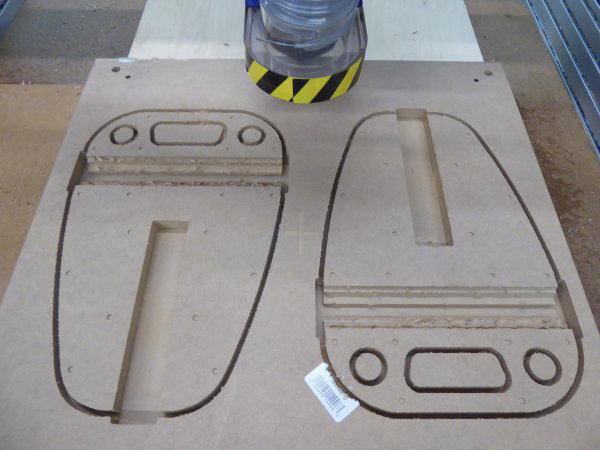
- All the 2D machining with the .25” end mill for the “Inside” of the model is complete.
- Since the roughing pass is a pocketing pass that will be smoothed over in the finish pass, it has been run with a .25” end mill bit rather than the .25” ball nose bit.
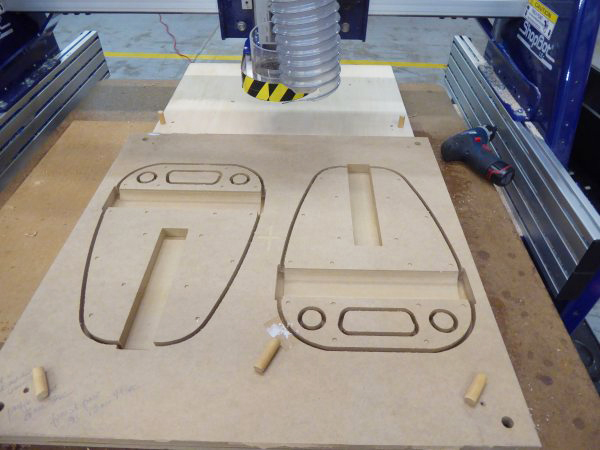
- Dowels are ready to be put into position so the board can be “flipped.”
- The board has been unscrewed from the temporary spoil board.
- The 3D machining (.25” ball nose bit) on the “Inside” of the model is complete.
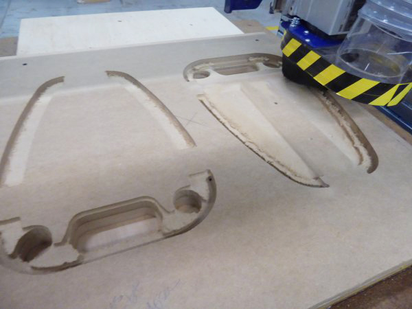
- Roughing pass on the “Outside” is complete (.25” ball nose bit).
- Note that the large holes at the top of the model are now completely open and waiting for their smooth over.
- Finish pass started (.25” ball nose bit).
- After this part of the machining is complete, long screws through the holes in the center of the models will be used to hold down the models while the models are separated from the substrate.

Completed samples viewed from the inside and the outside of the seat bracket.
The two sides fitted together.
**What Would I Do Differently?
Design time: It would have cut down on my design time if I had asked the customer to send the vectors that made up the original 3D model (.eps or .dxf format) in addition to the 3D model itself (.stl format). As it was, I had to use the tool in the Vectric software to define the edge of the component, or redraw the vectors I needed over the 3D component.
- In Solidworks, one can select the vectors from the model, and use SAVE AS to export them as 2D files (example: .eps, .dxf).
- In Inventor, one can choose to view the model from above, then hover the cursor above the 3D rendering. When the vectors are visible, right click to see the option to save as or export the vectors in .dxf format.
Toolpathing options: I would think through more carefully how deep to make the tool paths that go along the edges of the model. If I had made the 2D cut out on the first side I machined shallower (the “Inside”), then I would not have had to create two separate 3D finish passes near the edges of the second side (the “Outside”). I would still put hold down screws in the center of the “Outside” pieces so that the work did not shift when I ran the final profile to cut out the samples.
*** Setting Up the XY Zero Routine
If the automatic XY Zero routine using the proximity switches has not been set up on the ShopBot, now is a good time to do that. In the ShopBot Control software, click on Tools > ShopBot setup. Click through the screens to find the page that talks about setting up the XY Zero routine. Choose “Make it easy on me.” The program will let you use the keypad control to move the bit to where you want 0,0 to be and zero it there. (Click on the fixed distance button on the keypad to fine tune movements of the ShopBot.) Then, the program will test the distance between the 0,0 point and the proximity switches, and make it so you only have to use C3 or the icon on the position screen to zero the X and Y.
This is critical if you need the 0,0 to be absolutely accurate. By using the automatic X,Y Zero routine to give you a good starting point, then moving the bit to an exact location (M2, 12, 12) and setting the new zero there, you can always get back to that point in case of power failure or operator error.
Suggestions: How to Charge for a Project Like This
Although I did not have to create the original model, the expertise to figure out how to machine the model, and the cost of owning, maintaining, and running the shop and equipment to be able to do such a project should be taken into account.
- The materials (purchase and prep) and the bits all have to be covered.
- Shipping costs where applicable also have to be considered.
- I usually charge between $75 and $125/hour for design time and machine time (setup and clean up are also added to the actual machine time).
- For this project:
- Design time: Approximately 2 hours.
- Time to purchase materials and glue up board: approximately 1 hour.
- Actual time the ShopBot was running:
- Marking Hold Down of temporary spoil board: 0:00:15
- First attempt at holes for dowels on temporary spoil board: 0:00:24
- Redoing holes for dowels: 0:00:24
- Marking hold down of material: 0:00:15
- 2D files for side 1: 0:12:03
- 3D files for side 1: 0:13:04
- TOTAL SIDE 1 (Inside): 0:26:24
- Roughing pass for side 2: 0:20:00
- Finish pass for side 2: 1:20:25
- Final finish pass for side 2: 0:08:24
- Cut out the parts from the substrate: 0:03:00
- TOTAL SIDE 2 (Outside): 1:56:49
- Additional time added for set up, bit changes, clean up, etc.: Approximately 1.5 hours, including surfacing the ShopBot Buddy® table prior to machining the parts.
Tools in Vectric Software to Help Estimate Job
Compare estimate to realtime.
Leave a Reply