Assembling the Weekend Dinghy
Imagine being a high school student and having the opportunity to pilot a plane or a boat, learn how to design and model planes and boats, and understand the businesses behind the aviation and marine industries—all while taking core high school courses. Davis Aerospace and Maritime® High School, a unique partnership between Cleveland Metropolitan School District and PHASTAR Corp. presents that opportunity for students in Cleveland, Ohio.
In April, under a contract with TIES, I was able to spend two days at Davis to work with the teachers and digital fabrication lab managers. Our goal: to use the ShopBot CNC router (a PRSalpha) to build boats and create a model of the Cuyahoga River to float them on. Doing the research for how to make that happen was part of the fun.
PROJECT 1: Building Models of Boats
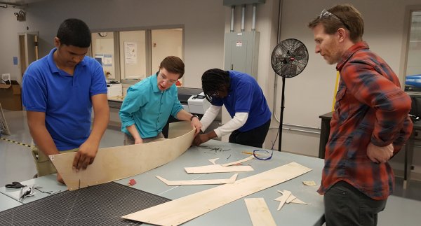
Danny and Nick, digital fabrication lab managers, showed me the progress that they had made translating designs on paper into models of boats. As shown in the photo, cutting out the models by hand, then taping the models together, regardless of how the plans were generated (photocopies or CAD drawings generated from paper copies), had its drawbacks.
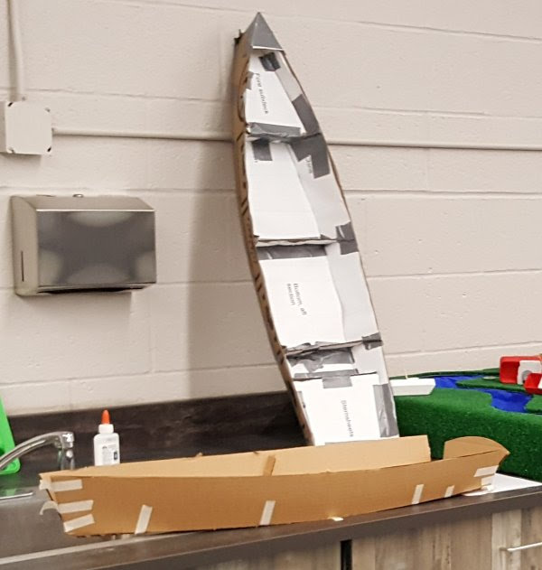
First attempts at creating models from paper plans.
Joining Long Pieces Together
Once a CAD file of the designs had been generated in Fusion 360, Danny and Nick (with Scott acting as cheerleader) had used the ShopBot to cut out a sample in plywood. With the intention of eventually making boats bigger than either the bed of the 4’ x 8’ ShopBot or a standard sheet of material, they had created their own version of a scarf joint. It was a great idea to use the precision of the CNC to create curves to interlock and join shorter pieces into longer panels. But there’s more!
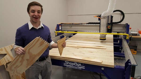
Scarf joint using the precision of a CNC tool.
Bill Young, a boat builder from Virginia who early on realized the potential of CNC woodworking, would add another dimension to the scarf joint. For his boat kits, he created scarf joints that beveled the edges of the material where two shorter pieces joined together to make a long panel.
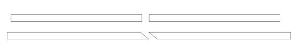
Scarf joint options. Straight butt joints, or beveled edges.
Then, Bill realized that he had the option of 3D carving (though he didn’t call it that) the scarf joints to increase the precision of the fit, reduce the chance of breaking off the tips during shipping, and disguise the joint in the finished product. Here is a link to Bill’s blog about his creative technique for creating “wavy” stepped scarf joints.
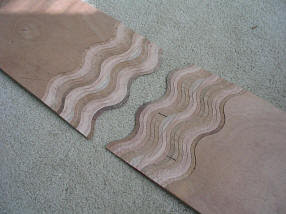
Bill Young’s wavy stepped scarf joints. Joints are machined from the top down, then flipped for assembly.
Holding the Parts Together During Assembly
Stitch-&-glue is a technique used by many boat builders who are creating “hard chine” boats: Panels cut out of flat material are designed or lofted with “developable surfaces” so that the curves of the panels will fit together when “folded” into 3D boats.
With a CNC machine, the panels can be cut very precisely so that there are no gaps or overlaps between the edges of the panels. As the panels are being cut, a series of holes can be added so the panels can be “stitched” together with cable ties until they have been glued in place.
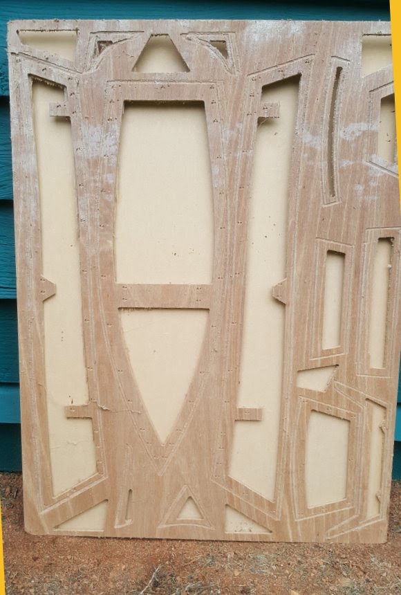
Once again, I looked to Bill Young for inspiration. A number of years ago, Bill had created a file to cut a 1/4 scale model of the “Weekend Dingy,” a 9’ skiff designed by Karl Stambaugh of Chesapeake Marine Design. The original skiff was built during several of the Woodenboat magazine community boatbuilding events, and Bill’s model kits and instructions were given away during the early Maker Faires. For this trip to Cleveland, Bill was able to find the original .sbp files, convert them to a .dxf, then import them into a Vectric file for us to try out at Davis.
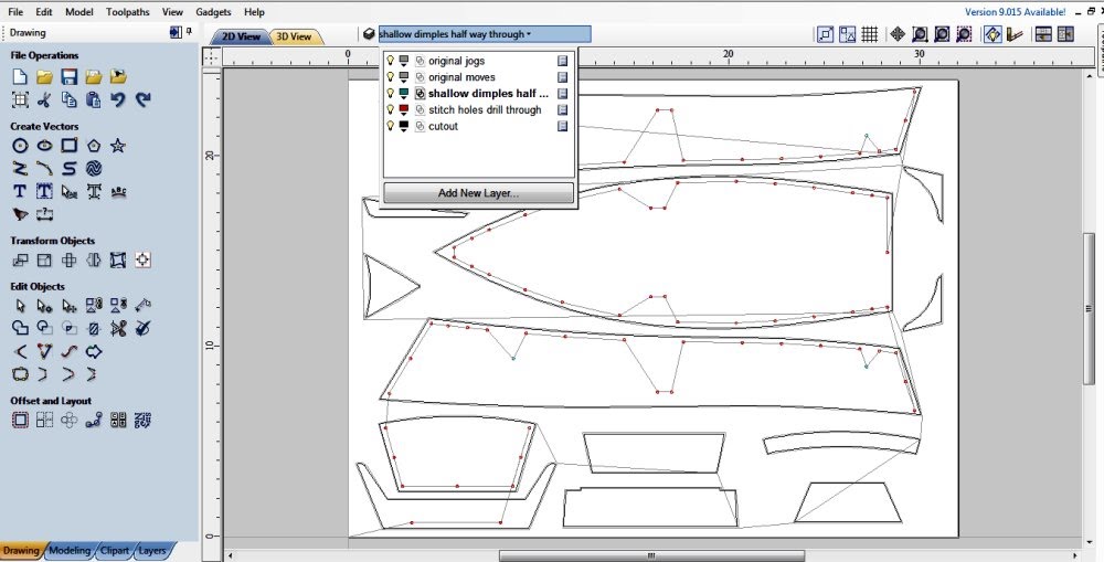
VCarve Pro or Aspire CAD file generated from original .sbp code.
- In the ShopBot Control Software, the FC command will convert a .sbp file to a .dxf file. That .dxf can then be imported into the Vectric software.
- The .sbp file includes the compensation for the waste from the bit. To get the true size of the design, the vectors that mark where to cut out the parts have to be offset to the inside the radius of the bit used in the original .sbp file.
- Anything that is just a plunge into the material, like a hole for the stitches, would not have to be offset.
- Once the true size of the design is determined, the model can be scaled up or down and re-toolpathed to take into account material and bit size as needed.
- Note the layers in the design file. Many of the layers were created from the .sbp to .dxf conversion. Some, Bill created to keep track of his work
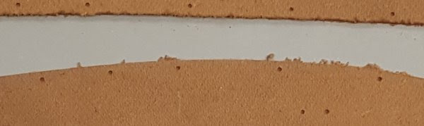
At Davis, we first scaled the model even further and tested the concept with tempered hardboard, easily available from the big box stores. Using a 1/8” bit, we used the drill toolpath to create the marker and through holes for the stitching (the size of the bit determines the size of the hole), and the profile-to-the-outside toolpath for cutting out the pieces. Didn’t quite get the cut depth correct, but not bad for re-engineering a 10-year-old file.
First test and detail of smaller model cut out of 1/8” tempered hardboard.
For the ¼ scale model, we used .25” inch Luan, again from the big box store. Without the vacuum hold down table and template that Bill had used for his Maker Faire kits, we marked where it was safe to put a hold down screw in the CAD file, had the ShopBot run a file to mark those locations on the board, and screwed the board to the sacrificial table. Since adding tabs to hold the parts in place while they were being cut out might mar the clean edge of the cut, we instead added a ramp to the profile toolpath to create a temporary functional tab at the start point of the cut. Nick also provided a physical assist to keep each piece in place while the cuts completed.
Vacuum template used by Bill Young for original Weekend Dinghy kits given out at Maker Faire. One could create a mini vacuum table much like the one described here, lay a template like this on top, then the material. When the parts are being cut out, the toolpath cuts into the template, and the parts are held in place by the vacuum.
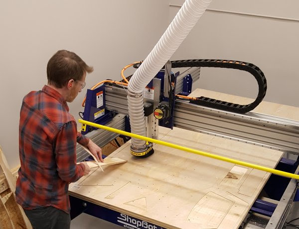
Nick is using a board as an assist to hold the parts in place as they finish cutting.
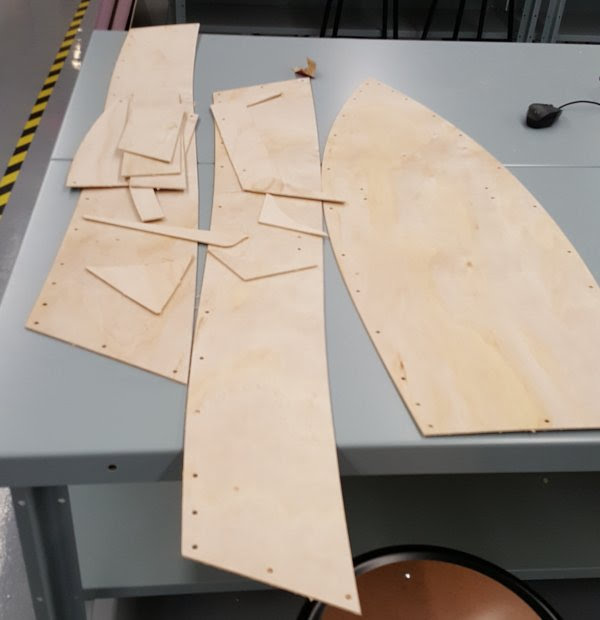
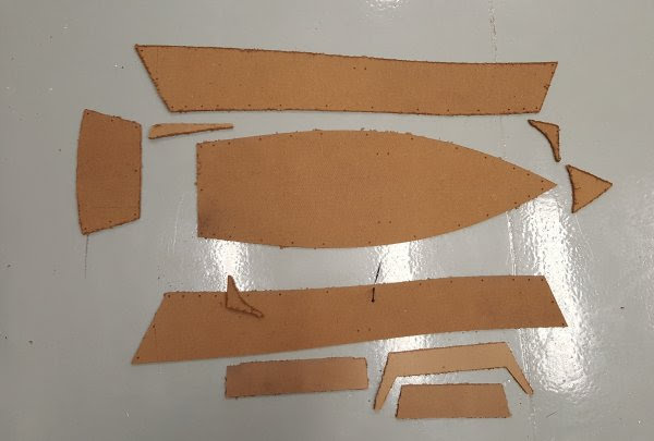
Parts ready for assembly.
Members of the after school club assembled the boat using cable ties and intuition. (So why did Bill provide instructions?)


The school now has a project that they can share with their students, and with the community at large. It was also a terrific opportunity to revisit the ShopBot website for ideas and information about boatbuilding, including the original inspiration for why Ted Hall created ShopBot Tools.
PROJECT 2: A River to Float Them On
Danny and Nick showed me the 3D printed and laser cut boats the kids had designed, and a hand-carved model of a big bend in the Cuyahoga River lined with a plastic table cloth and fake turf. Danny reported that it was successful at first, but the plastic table cloth was water resistant, not water proof. All too soon, the water leaked out of the model. Still, the students were able to test concepts about size of craft, displacement and maneuverability around the objects, and geography of the river.
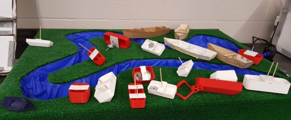
First attempt of creating a model of the Cuyahoga River in downtown Cleveland.
With the ShopBot, Davis wanted to create a bigger version of the Cuyahoga River to test larger models. Adding semi-realistic information on the depth available to float a water craft, and the height of the bridges they have to get under, would make the model more meaningful.
The first step was to locate a digital model of the river that flows through Cleveland and into Lake Erie. I tried Terrain2STL, a website that takes information from Google Maps and turns it into 3D files that can be printed with a 3D printer or 3D carved on a CNC. Cleveland is too flat for much detail, and the site wouldn’t give underwater data either. I also looked at Google Maps, USGS (US Geological Services) for topographic information, and NOAA (National Oceanic and Atmospheric Administration) for a chart of the Cleveland area that would be useful for mariners piloting Lake Erie and the Cuyahoga River. No one source was sufficient, but combined, they gave us a lot to work with.
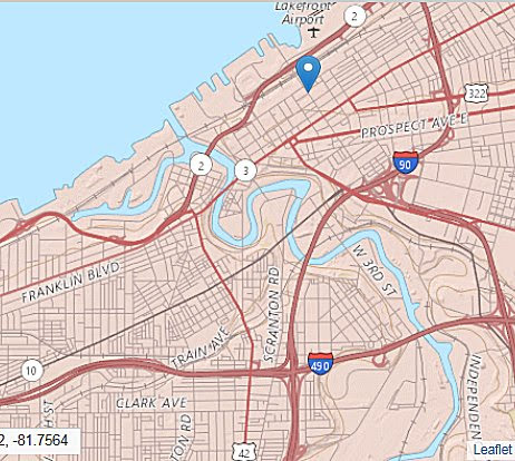
USGS map of Cleveland waterfront. Location of Davis Aerospace and Maritime High School is marked.
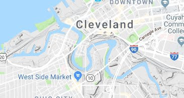
Google Maps version of Cleveland.
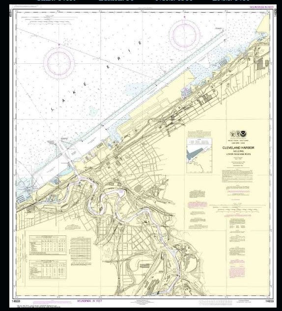
Chart of the lower Cuyahoga River and Lake Erie water front with water depths, bridge heights, and landmarks as seen from the water. Pronounce NOAA as a man’s name. Who says the government doesn’t have a sense of humor?
Once we got a semi-clear image of the banks of the river, we brought it into VCarvePro for tracing. With the vectors, we could select the portion of the river we were interested in, and scale it for the size of material we have available. For our first attempt with a small piece of pink insulation foam, we were ready to use a pocketing routine and a ball nose bit to scoop out a model of the river.
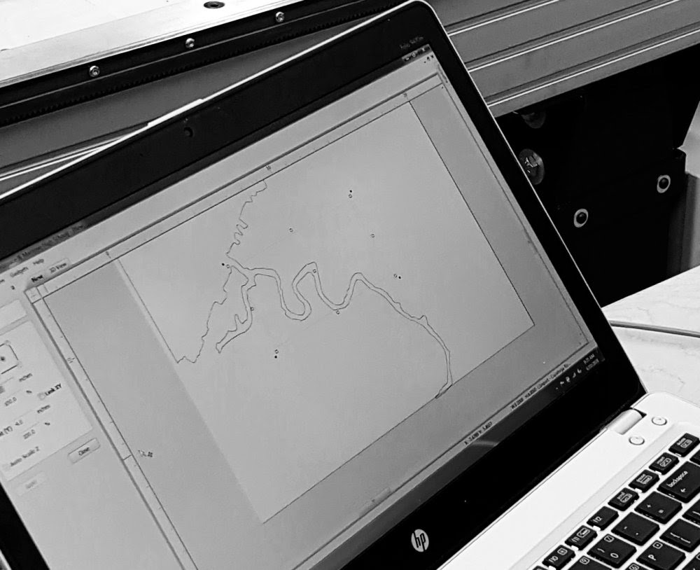
Outline of the Cuyahoga River traced in VCarve Pro. Next step is to select the area of interest, and set up for pocketing in foam.
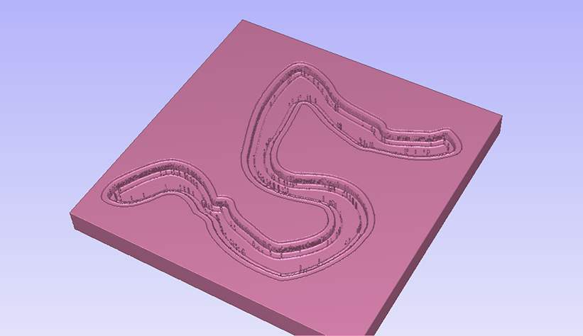

Pocketing the selected area at three different depths with a ball nose bit and a large stepover using a contour path (hence the visible lines).
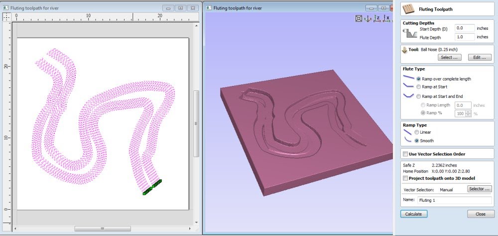
Since the model was a 2D vector and not a 3D rendering such as an .stl, with VCarve Pro, in this first attempt, we could only use 2D toolpaths that machine to one depth. However, the Vectric softwares have a toolpathing option called Fluting that will vary the depth of a single open vector from one end to another. Simulations indicated that, with a little manipulation, it would work to give us a river that was shallower upstream, and deepened as it neared the mouth.
Using the Fluting toolpath to vary the depth of the River
- We created a series of open vectors inside the boundary of the river, and made sure the start point of each vector was on the upstream side (green point)
- Choosing all of the vectors, we set the start point at 0 (top of the material) and the flute depth to 1 inch
- Fill in the blanks, toolpath and simulate to check the results.
- Adjust as the simulation reveals more about the results
The Professional Development was directed towards the faculty of the school. It was fun time when, each day, students visited the Fabrication Lab while we were working. Some even got involved in doing a quick project.
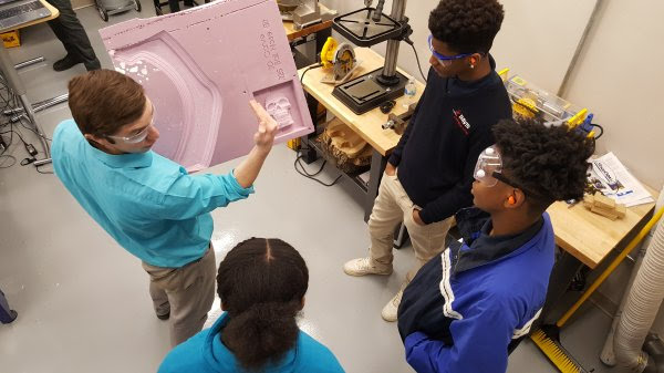
Danny showing the students examples of the ShopBot carving in foam.
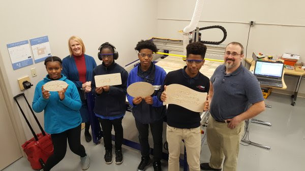
Students design and machine their individual signs. It was terrific to see how well Scott knows his students, and what motivates the reluctant ones.
This year was the inaugural year for Davis Aerospace and Marine® High School, starting with approximately 60 students in the 9th grade class. Each year will add another class until there are 4 classes/years. Applications for next year’s class are now open. I’m sure Bill Young (and I) would be glad to visit again and keep up with the progress.
Leave a Reply