As we use our CNC’s we learn that we can assign virtually any position to any axis at most any time. We usually have a reason to do this, like a special purpose jig, or room for clamps for relocating the X & Y axis, but we routinely reassign the position of the Z for most every file we cut. Notice that I said, reassign the position of the Z axis rather than rezero the Z axis. I say this because in the complete range of Z axis travel, there are a finite number of zero locations.
Simply said, your zero location should normally be between the table and its upper limit of travel. If you have 6 inches of travel, then you cannot zero higher than 6 inches or below the bed. There are of course, other factors, but for normal cutting, these are the upper and lower limits.
Now for the relativity. Unless you have the world’s best eyeball, you can’t actually zero to the bed or an object, you zero to the Z zero plate. The control software has been told the thickness of this plate and it sets the position that it electronically senses (the top of the plate) as that thickness. The actual zero position is set relative to the top of the plate, by its thickness, to be the bottom of the plate. The same logic applies to fixed zero blocks. Its position, relative to the table surface, is adjusted for in the software during the zeroing routine.
Contrary to popular belief, zeroing a bit to any plate or block is very seldom exact. Due to electronic timing, the downward motion does not always stop at the exact same spot every time. Some bits dig into the plate. The plate can bend or have a low conductive spot on it. The bit can be coated. Individual control boards can react to the input signal with minute variations. All of these items can result in a few thousandths variation of position. Even more if one or more of them add together instead of canceling each other out. In most conditions, you can expect 10 thousandths either side of zero as the norm, 5 if you do some tweaking of your zero file and procedures.
These minute variations rarely affect our cutting until we wish to do a pocketing operation with multiple bits. Although irritating, it is common to see a second bit cut at a different depth. As users we need to develop methods to check for inaccuracy prior to cutting.
These electronic variations are nothing compared the variations in most processed materials, especially sheetgoods. It is not uncommon to see 30 to 40 thousandths thickness difference in a single sheet, even more across multiple sheets. More yet in inexpensive imported products. Our problem as operators is to find the actual or average sheet thickness from edge measurements. I usually take multiple measurements and average them to get my design thickness. In many cases, I have had to readjust the sheet thickness after cutting to reflect the actual material thickness in the interior of the sheet where my parts are cut.
Most sheetgoods cutters zero to the bed because we seldom know the real thickness of the material in the selected zeroing location. There are also variations with hold down due to material porousity. Prefinished and melamine are sealed, allow more vacuum to develop and therefore, suck down tighter than unfinished veneer plywood. Once a sheet is on the bed, should any problem, like position loss or broken bit occur, it is virtually impossible to rezero to the Spoilboard without removing the sheet. This is why most cabinet cutters use a fixed zero block, usually off the one end or side and below the surface of the Spoilboard so that it does not interfere with table surfacing.
The points that apply to the majority of users are this: Unless your material has been surfaced by the CNC you cannot assume that it is flat. Nor can you know the actual thickness at the zero location. These two facts added to the above electronic variations are the reasons for most of the depth inaccuracies facing small CNC users. There are also a number of variables associated with spoilboads, but we can save those for a later day.
As likely as a sheet cutter is to zero to his Spoilboard, most other users are not. There just seems to be something “off” with the way that most CAM packages treat zero to bottom of material. My experience is that it is harder to learn and more prone to error. Maybe it is just that we are programmed to think from the top down into the material. Even though I tested a number of files, my results were less than satisfactory and I followed the masses and prefer to design from the top.
I wanted the extra accuracy that zero to the bed gave me, but I also wanted the ease of use that I was accustomed to with zero and design to the top of material. There is a third way that allows both. Allows me to zero to my Spoilboard and then check the bit height against the Spoilboard in multiple locations prior to cutting. It also allows me to design my cutting files from the top of the material. It allows me to cut different thickness materials without a rezero of the bit. This method ensures that my actual bit zero is at the design thickness of the material. It does not eliminate errors cause by variations in that material, but will keep all other variables to the bare minimum.
I learned about this while beta testing for the ShopBot Link from the Thermwood programmers. Their files are all zero to bed, design and cut from the top. With their help I was able to understand the principle and implement it into my own Vectric post processors.
Here’s how it works:
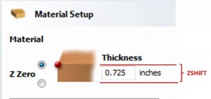
The Vectric Software outputs the design thickness of the material to the post processor. The PostP, using some of the new features of the SB3 software applies a temporary offset called the “ZSHIFT” to the Z axis for the duration of the cutting file. When the file is complete the offset is removed. For the duration of that file, the Z zero is actually at the top of the material. If your next file uses the same bit, but a different material thickness, no rezero of the Z axis is required. The only time a rezero would be required is when a bit is changed.
So…. My theory is that the Z Zero should be automatically relative to the material thickness. Here is a screenshot of the Vectric material setup dialog showing that zero to top is selected. The red lines show the offset that the ZSHIFT applies.
This feature works with both MTC and ATC files, but may not be in the mainstream files distributed with the SB3 software. As such, it is most likely not supported by ShopBot. This means that you either need to be or know someone that can modify your post processor. Or, you can borrow a copy from someone that is using it. Although very seamless when installed, there is a certain amount of expertise required to modify the post and implement the changes. And did I mention no tech support? Enjoy!
Leave a Reply