 No setting in the ShopBot control software (SB3) has more influence over the performance of your CNC than the VR [Values Ramping] command. I have no doubt that you’ve heard about ramping before, and to many, the idea of adjusting your VR settings is downright confusing and to some, scary. There seems to be a myth that somehow you are going to permanently ruin your CNC if you adjust the ramps yourself and get the settings wrong. This article is going to dispel that myth and help you get your CNC to move and cut the way that you want under a number of different conditions. There are a number of factors involving ramp values [VR] that are too complex to convey within this column. However, it is my goal to give both new and seasoned users a glimpse into your ramp settings and how you can tune them for the type of work that you do. Keep in mind that your ability to observe how your tool moves when adjusting ramps, is the key to tuning your tool for the exact type of work that you do. It is your responsibility as an operator to tune the tool to fit the needs of your work. ShopBot did an excellent job with baseline settings, now that your CNC abilities have grown, it’s your turn to get your tool dialed-in like a pro.
So, what is ramping? Within the context of this article, ramping refers to the manner in which your tool starts, stops and regulates movement using the SB3 control software. Just to make a distinction, these are ramps in speed. I will not be discussing cutter entry ramps, where your tool moves in an XZ or YZ 3D incline into your material to reduce stress on your bit when plunging. In order to grasp many of the concepts that I will be discussing, you’ll want to familiarize yourself with the [VR] command in the Command Reference PDF, found under the Help menu in SB3. You can also access it by typing HC into the yellow command box in SB3. You will also want to read, “Ramping – Detailed Explanation” starting on page 21.
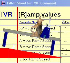
Let’s first take a look at a graphical representation of a typical ramp shape, showing the speed the tool moves in relation to distance:
If you typed in [MX, 48] into SB3, your tool will start moving at XY Move Ramp Speed, accelerate according to the Move Ramp Rate you’ve set (Ramp Rate being the slope of the acceleration line), run at the Move Speed [MS] you have indicated in your part file, then decelerate at the set Move Ramp Rate to the ramp speed where it stops at 48 inches. The illustration above shows the simplest ramp shape that your tool will make.
There are things that you must consider when pondering move speed [MS] and ramps [VR]. Just as you cannot make your car go from zero to 100 to zero again in a convenience store parking lot, you cannot make your CNC go from zero to 12 IPS to zero again within 8 inches. SB3 is smart enough to not allow the tool to make these types of aggressive moves. It will look ahead and set an appropriate course of action when you ask it to do something that violates the basic laws of physics.
Working with the [VR] Command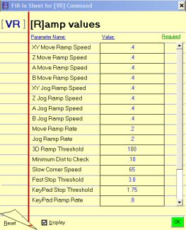 Here are the default VR settings for a PRS Alpha CNC. These are the settings that most influence cutting. Settings for a PRS Standard machine will vary slightly, but you will be able to apply the same concepts to your tool.
The occurrence of a ramp is influenced by a number of factors, but especially by a change in the direction the tool is moving. If you set your tool to move at 4 in/sec in XY when cutting out a 24 inch square with sharp corners, then your tool will move 4 in/sec on the straight sections but will ramp the direction changes going into and out of the corners (decelerate into and accelerate out of the corner. Curved corners, circles, and arcs will trigger ramps if they are tight, but in other cases ramping will not take place if you are cutting a large enough arc or curve. We will discuss this in further detail later in the article.
But back to the [VR] Fill-in Sheet. Starting at the top of the sheet, we have the XY Move Ramp Speed (MRS). Here it is set to 0.4 inches per second. This setting essentially sets the starting speed of your tool when moving from a dead stop. It is often helpful to lower this speed value when you are machining intricate or small parts, or machining very dense materials, such as non-ferrous metals, since it will reduce cutter deflection. It is also helpful to lower this value when you are using small cutting tools under 1/16” diameter. The downside to setting this value too low is that it can start the tool out too slowly under general cutting conditions and it will take longer to get up to speed, making the tool feel sluggish. Only modify this if you need to.
The next three settings do the same as the XY Move Ramp Speed, but correspond to their indicated axes. You may find it helpful to lower both the XY MRS and the Z MRS when doing small or intricate v-carving. For most 2D and 3D cutting, it is not necessary to adjust the Move Ramp Speed.
The next four settings influence jog moves, and they are best left alone.
Let’s have a look at the next setting, Move Ramp Rate. This setting defines the acceleration and deceleration rate for ramping as a distance. It essentially tells SB3 how much room it has to speed up or slow down the movement of your tool, by two speed units (2mm/sec or 2 in/ sec). By increasing the Move Ramp Rate, you are making ramps longer and smoother. This adds a sort of cushioning effect to the tool’s movement. By shortening the Move Ramp Rate, you make tool movements more aggressive, which may or may not be desirable depending on the part you are cutting. The default 0.2 value is a good general setting. If you are doing 3D relief carving with many moves in the Z, you may want to experiment with lowering the value to 0.1 and checking the cut quality of your parts. [Tip: It is important that you have your v-roller bearings on your Y and Z axes adjusted properly to eliminate any slop and vibration that may get transferred to your cut part when doing aggressive 3D]. For most parts, the 0.2 default setting works well.
The Jog Ramp Rate functions well at the default setting of 0.2 and is best left alone.
Let’s move on to the 3D Ramp Threshold setting. This setting controls how sensitive ramping is in the Z axis when cutting 3D reliefs. The higher the value, the more responsive and less sensitive to ramping the Z, A, or B axes will be when cutting. The default is 100, I like 150 as a good general setting for most 3D files. Keep in mind that your move speed (MS) will influence 3D ramping if the Z axis cannot respond fast enough to XY movement. If you are rastering over a 3D relief and meet an abrupt wall or large change in Z height, and your Z move speed is not fast enough, SB3 will trigger ramping to occur, and this will slow down the XY movement to match what the Z axis can handle. More on this later. There are situations, where increasing the 3D threshold is very useful. If you have a relief with a lot of little moves, such as one with a background texture, where the Z has to move up and down quite a bit, an increase in the 3D Threshold can help to speed things up, provided that your Z speed is high enough where the XY doesn’t have to slow down. For most reliefs, however I have not found that increasing the 3D threshold to be beneficial. In many cases, increasing the 3D threshold beyond a value of 200 when cutting a low detailed relief can result in jerky Z moves, and in other cases not influence the movement of the tool at all. Use your best judgment, and experiment with settings for the type of work that you do.
The Minimum Distance to Check (MDC) setting works in conjunction with angular movements and basically adjusts when ramping will happen based on the tightness of the corner. It will influence ramping when very small bumps, curves or jagged features are present in your cutting file. The larger the number, the more likely you will get ramping with small curves or features. The default is 0.1 and I like to set this to 0.08 to since I often work with very intricate designs. This adjustment reduces the tendency for ramping. The MDC setting also adjusts the speed that very small circles will be cut at since a small circle is basically a continuous tight arc. Making the number smaller will mean that small circles are less likely to ramp.
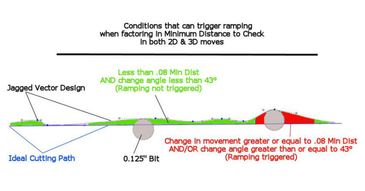
The illustration below shows how very detailed 2D & 3D models can cause jagged cutting and even tool vibration, if the minimum distance to check value is set too high. The example below shows a 0.125” bit cutting a span of jagged vector nodes. The ideal cutting path is suggested as a straight line. The green areas indicate movements less than the MDC and the red areas show the 0.125” bit making a movement change greater than the MDC. Rather than over-think the Minimum Distance to Check value, set it to .08, as I have found this to be a good setting for all types of cutting.
The sharper a corner the more the tool will slow down. In a tight angle, the speed will slow to the Ramp Speed for the primary axis and type of move. With a slight angle or gentle curve, there will be a slight slowing. The amount of slowing is the Slow Corner Speed (SCS). SCS is a percentage value of your move speed (MS). The default setting is set at 65%, which I find to still be a little too fast for me. The SCS influences how fast the tool will traverse a corner in both 2D profiling and 3D profiling. I have found that anywhere from 25-65% is a good range for just about any type of cutting you will need to do. If you find that your tool is taking corners a little too quickly, then you will want to reduce the SCS value. While this is not much of an issue on a PRS Alpha, standard PRS tools can reduce the chance of lost steps by reducing the SCS, especially when cutting aggressively in sheet goods or high-speed 3D raster movements. The SCS will add a bit of cushion at the end of raster moves, and slow down your tool in the corners, drastically reducing cutter deflection. I often lower the SCS to 40-50% when cutting 2D parts, and between 30-45% when cutting in 3D, since I find that it eliminates or greatly reduces the tendency for the tool to ‘bang’ when it meets a sharp wall of a relief carving.
Specialized Settings for STOPS and KeyPad. The last few settings in [VR] define some specialized threshold settings. The Fast Stop Threshold sets the highest speed where your tool will instantly stop when you hit the Space Bar or the E-Stop. At higher speeds you will get a ramped stop and a Z axis pull up from the material followed by the router/spindle being turned off on tools with spindle control. This type of ramped stop can always be triggered via the S key. The default setting has been 3, but ShopBot has recently changed the default to .2 so that all STOP conditions will trigger the same, safe, ramped stop with Z pull-up and spindle turn-off. You can still set the value higher so that for special conditions you can have an instant stop. However, values above 3 are not recommended as this puts a lot of shock into the drive system.
The remaining two threshold settings apply for KeyPad [K or SK] mode only. They adjust how the tool responds when moving the tool around with the arrow keys. The Keypad Stop Threshold is very similar to the Fast Stop Threshold. The default is 1.75 IPS, I’ve bumped mine up a little to 2 IPS. The Keypad Ramp Rate is similar to the Move Ramp Rate, and it controls how quickly the tool will accelerate and decelerate when moving the tool with the keyboard. The default is 0.8, which I found to be too soggy. I set mine to 0.2 for crisp movement. However, some people prefer the slower response because it allows very precise small moves.
My approach to VR Settings
Now that you have a basic understanding of how [VR] settings can influence your tool, let’s talk about some of the settings that I use for different types of cutting. Generally speaking, the settings that influence the movement of the tool the most are Slow Corner Speed, and Minimum Distance to Check. Most of the time, I will only adjust the Slow Corner Speed, after I have set my values to the numbers I have suggested throughout this article. 3D cutting is a bit more involved, since dialing in [VR] for every type of 3D file you may encounter is tough. By this, I mean, running the tool as fast as I can with the best finish quality, without watching my tool beat itself to death with vibration. For most 3D reliefs, the settings I suggest in this article are adequate. Files that have a lot of surface or background texture will benefit from a higher 3D Threshold value, a lower Move Ramp Rate and a higher Slow Corner Speed. If you find that your tool sounds too rough for your liking, return the Move Ramp Rate to 0.2. If it is still happening, reduce the 3D threshold to 175 and if it is still happening, reduce the Slow Corner Speed. These settings have the most influence over 3D cutting. Additionally, since the Minimum Distance to Check also works in 3D, you may want to try lowering the value so that it is less sensitive to those little details in the background.
I want to take a moment to talk about move speeds [MS] and 3D cutting. Getting your move speed set correctly in your part file is just as important as getting your [VR] dialed in. If you set a MS, 6,3 in your file that cuts a 6 inch wide relief, cutting will not be smooth or as expected for two reasons. One, the XY speed is too fast for the size of the ‘parking lot’ and two, the XY speed is 2X the speed of the Z axis, forcing the XY to slow down while the Z axis tries to keep up. Depending on the type of relief you are cutting and the amount of detail, here are a few speed combinations I have found to work, without symptoms of the tool slowing down to wait for the Z axis: 2,1 – 2,2 – 3,2 – 3,3 – 5,3. Unless you are cutting very large or long 3D parts, you probably won’t get over about 5 IPS. 3D cutting is very different from 2D cutting since the tool has to fight gravity and push and pull a gyroscope (your router) into your work at a high rate of speed. If you make sensible decisions about your move speed and adjust [VR] by observing the movement, sound and smoothness of your tool, you can transform your CNC to match the type of work that you do.
Saving Your Specialized Settings to Use at Another Time
OK, so you have your [VR] settings dialed in for perfect 2D cuts. You can type in the US command and save your configuration with a meaningful name, like ‘Brady2D.sbc’ and then move on to tune your tool for the type of 3D cutting that you do. You might want to save a configuration for V-carving and another for 3D relief cutting as well. After you have saved each configuration, you can easily call it up by typing in the UR command. It will ask you if you want to reset the current configuration. After affirming that this is what you want to do, you will see a list of configurations that you can choose to load, including the ones that you saved from your tuning sessions.
My next report … under wraps