You saw the round parts and jigs I was making in the last article. All of them were made without the help of a CAD/CAM package. I only used the keyboard and the ShopBot control software. I am running 3.5.3 which is the current release as of today, and I find it quite an improvement over the release that shipped with my machine more than a year ago. The team at ShopBot have sure kept the “thinking cap” on. Now let’s get started.
I move the machine to the X and Y location that I want to be the center of the part.
When I type “CP” into the command box in the ShopBot control software I will get a Fill-In sheet.
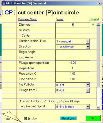
“Diameter” is, of course, the diameter of the cut I wish to make.
The “Xcenter” and “Ycenter” boxes can be left blank and the tool will use the current position. You could enter values here and the tool will move to that spot and then cut.
“Outside-inside-true.” I will be using the outside because I am going to cut an 18.5” circle now.
“Direction” will be left at “default.” I could have selected “CW” or “CCW” for a climb or conventional direction of cut.
“Begin Angle” I have left blank since I am cutting a circle and don’t care where it starts cutting from.
“End Angle” will also be left blank. This will cause the machine to cut a circle.
“Plunge.” This command is worth making a note about. This value tells the tool how much to go down on each pass. Sounds easy, and it is, until you forget to make this value a negative number and you watch to tool go up on each pass. It is hard to cut something if the tool goes farther away from the wood each time.
“Repetitions.” How many times do you want the tool to go around? If I had the Z .25” above the surface of my material I wanted to cut, had the plunge value set to .25” and I wanted to cut through .5” material, I would need to go 3 repetitions. The first one would go to the surface and the second one would go .25” into the material and the third would be .5” deep. There is another way to do this and, that command is coming up shortly. It is plunge from 0.
“Proportion X and Proportion Y.” I wanted the size to be what I had entered into the diameter box so I left this at “default.” I could scale up my circle by entering values here.
“No Pull-Up.” This command made me think of my old HP 25 calculator that used RPN. This catches me off guard so I always read it twice and think about it. The box is asking you if you want to have the Z pull up after the cut is finished. So, “No Pull-UP” should be “OFF” if you want it to pull up after the cut.
“Plunge from 0.” Here you can instruct the tool to go to the Z-zero position and then start your cut. In my example, I used the current Z position of .25” above the material and just made three passes. I could have set this option to “yes” and have done two repetitions with a -.25” plunge. My example here will take into account material that is thicker or thinner than the exact .5” since it starts .25” above the surface.
“Special: Tabbing, Pocketing, & Spiral Plunge.” These are pretty cool features. I use the pocketing and spiral plunge with bottom ones the most. When I cut wheels for my toys, I use the spiral plunge with bottom. This causes the Z to go deeper as the tool moves around the circle. It does not just plunge and go around. I find this puts less pushing force on the small parts and makes them easier to hold down. Spindle owners will love this as they don’t want to plunge the spindle down hard and deep but rather ramp into the cut.
Now, in my opinion, we get to the most important commands of them all. But you may say, “there are no more blanks in the fill-in sheet!” And you would be correct. No I am not crazy, but this did drive me crazy for a while. Do you recall we never told the tool how fast to move or what size cutter you placed into the collet? Try cutting an 18.5” disk and allowing the machine to think it has a .5” cutter in it, while you actually have a .25” cutter in it. And try that at 10ips. Look to the right side of the fill-in sheet. There is a scroll bar. Move it all the way down and you will see a couple of notes.
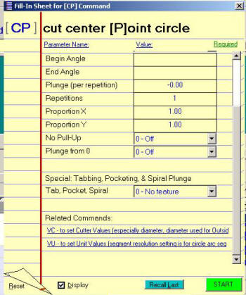
“Related Commands.” You had better go and look at these related commands because you will not get what you think you will without doing so. And remember to do this each time you use this command or any of the others that are built in. They all get the speed and cutter information from there. I hope in some future release of the control software there will be either an indication of the bit and speed or maybe even a fill-in for the cutter and speed.
So by using the “CP” command to cut circles and pockets and the “CR” command to cut squares, I was able to make my jigs and fixtures as well as my parts and never open up Corel X3, Vcarve PRO or PartWizard. I am not saying you don’t need a CAD/CAM package, because you do for some jobs. They make life easy. All I am saying is go and explore the power of the control software you have right in front of you.
Maybe at some future Jamboree there could be a contest centered around making something without using any software other than the control software and its built-in commands. Hmm, I might have to suggest that.
Ed