
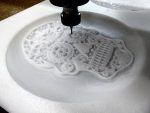
Slide together steps prototyped and produced during July’s Digital Fab for Educators.
Traveling to Durham, NC from Baltimore, MD with his wife and elderly dog gave one of the July 2017 Digital Fabrication for Educators Workshop attendees, Frank, an idea of what to create during the workshop at ShopBot. The old girl (canine) had a difficult time getting into the back seat of the car, and helping her by lifting her hind end into the car seemed to cause her pain. So Frank decided to design and fabricate a set of slotted stairs that he could assemble without hardware.
Frank used SketchUp to design the steps. Since SketchUp is a 3D rendering CAD program, he could view the design from several orientations, as well as change the thickness of all linked components (like the slots) in one fell swoop. Plus, it is easy to import a SketchUp file (.skp) into VCarve Pro for machining in 1/2” plywood. Once he had all of the parts, Frank scaled them down so that he could use the Epilog laser to cut a prototype in cardboard. He then exported the vectors from VCarve Pro in .eps format to bring them into Corel Draw for “printing” on the laser cutter.
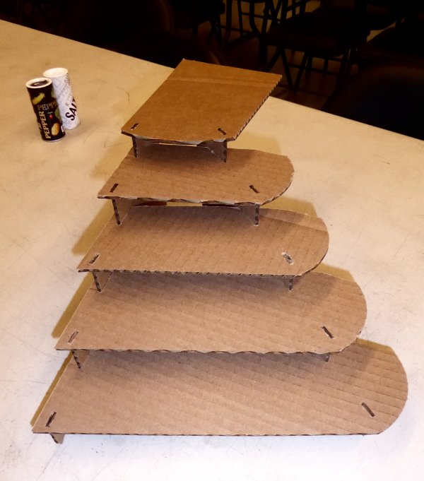
Cardboard model of car steps.
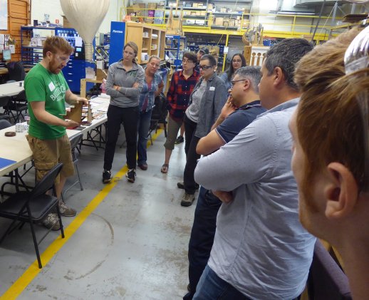
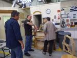
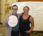
Frank talking to the class about his cardboard prototype cut on the laser cutter. Thank you to Epilog laser for loaning ShopBot a laser for the workshop.
Once he was convinced that the design would be stable and easy to assemble, Frank set about prepping it for machining on a ShopBot. The first step was to test that the slots were the correct size for the half inch sheets of plywood that were available in the shop. Sallye (the workshop instructor) helped him to create a test piece that could be fitted onto the edge of the plywood to determine what size to make the slots so that the pieces fit together easily and without too much slope.
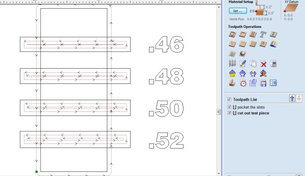
Start with a larger rectangle that defines the total size of the test piece. For the slot sizes, create a series of rectangles of different heights that extend beyond the test piece. (See below for why the width of the slot test pieces extend beyond the test piece.) Toolpath the slot test rectangles as a pocket that goes about halfway through the test piece. Use “profile” to the outside to cut out the test piece. Remember to use the same bit and cut direction for the test cut that will be used for cutting out the final parts.
Clicking the solid box in the lower right corner of the toolpath screen will show what the bit will actually machine away. Note that the radius on the inside corners of the slots. By having the slot test rectangles extend beyond the actual cut out, the rounded inside corners will be cut off when the test piece is cut out, so the slots will fit on edge of the board.
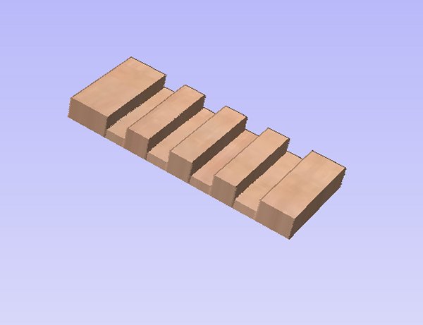
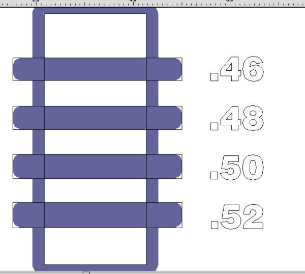
A simulation of the resulting test piece. Mark the slot sizes with a permanent marker, and indicate which bit (size and geometry such as up or down spiral) and cut direction (climb or conventional) was used for future use.
The half inch Baltic birch available was actually a 1/2” inch thick, so the slot size did not have to be adjusted in the original CAD drawing. Frank used VCarve Pro to add dogbones to each of the inside corners to allow for a square edge to fit into it. Then, he laid out all the parts on the 4 x 8 sheets of plywood and set the toolpaths to machine with a 1/4” down spiral bit.
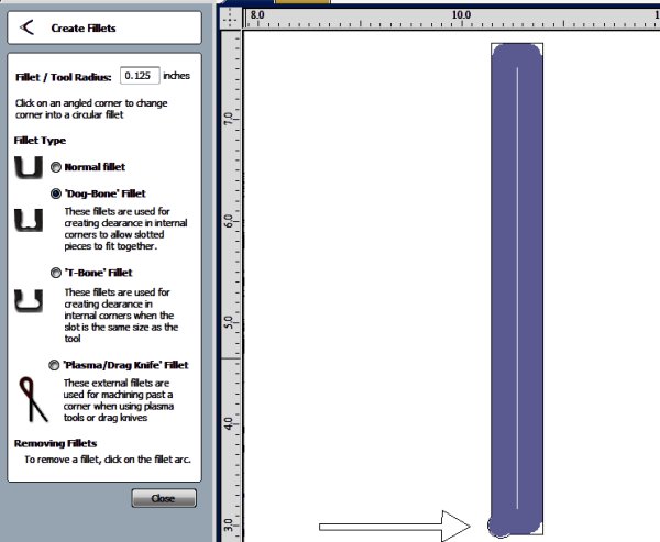
The closest that the spinning bit can get into an inside corner is the radius of the bit. Adding a dogbone to each inside corner creates space for a square corner to fit into the slot. Look under the “Fillets” icon to find the dogbone feature.
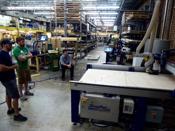
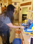
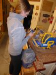
Watching ShopBot’s production tool with Automatic Tool Changer (ATC), vacuum hold down system, and dust collection cut out the parts is a group activity.
The actual machining on ShopBot’s production tool with Automatic Tool Changer and vacuum hold down system took a matter of minutes. After a little sanding, a group took the steps out to his car for a test run (as seen in the photo at the start of this blog post). Frank found he could assemble his steps in a minute and a half. The half inch plywood flexed a bit more than he would like for his 50 lb. dog, but another attendee, Kirsten, suggested that he use plastic drink cups as supports to increase the structural integrity of the wider steps. We can’t wait to hear (and see) how his pup likes her new stairway.
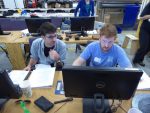
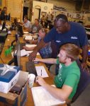
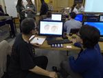
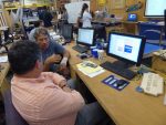
Below are more pictures of the projects completed and the friendships made during the 3 day workshop.
-
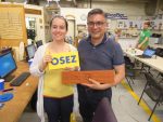
- Dare (Oser) to take part in this workshop.
-
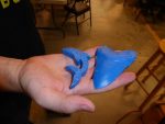
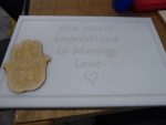
- 3D Carving of a cultural symbol for molding and casting.
-
- Handibot station
Leave a Reply