One of the tasks at which the ShopBot excels is processing sheet materials. I love that I can slide a sheet of melamine or plywood onto the table and a few minutes later pull off a small pile of parts, ready for edgebanding and assembly. If you have done your design and programming properly all the machining operations – holes, dados, rabbets, notches, pockets, joinery, etc. – are completed by the machine before the parts are cut to shape and size – as long as they are all on the same face of the sheet. However, when processing sheet goods it is virtually inevitable that you will need or want to perform operations on the other side of at least some of the parts. Often these back-side details are referred to as “secondary operations” since they normally are performed on the individual parts after the parts have been machined out of the full sheet. More colloquially they are called “flip ops” since you have to flip the part over to machine the other side. In a larger shop these secondary operations might be performed on a different machine, freeing up the primary machine to start cutting the next full sheet. They might even use a different primary machine such as a beam saw to quickly cut large quantities of rectangular parts and use the ShopBot or a similar CNC machine to perform operations only on those parts that need them. In any case there is a big difference between cutting parts from a full sheet or an oversized blank, and machining operations on a part that has already been cut to its finished size and shape, primarily when it comes to locating the operations accurately on the part.
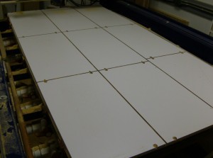
A few minutes ago this was a full intact sheet of white melamine. Now it’s a stack of parts ready to be edgebanded.
When cutting out of a full sheet or a larger blank, the same machine performs the operations and then cuts the outline of the part without the part moving in between, so even if the sheet is not located precisely on the table, or the machine is not zeroed perfectly to the reference point of the table or the sheet being cut, the operations will be in the correct locations on the part. With secondary operations there are serious issues of registering the part correctly on the table, and having the machine calibrated accurately, so that the operations are correctly located in relation to the edge or corner of the part. After all, what’s the point of using CNC equipment to process parts if the parts aren’t going to fit together perfectly, or the holes aren’t going to be precisely in the right place?
So a lot of effort is made to address these issues when secondary operations become part of a production setup. Let’s look at the two issues I mentioned separately. First, we have to ensure that each part is positioned exactly in the same place relative to the table of the machine. On a dedicated secondary machine this should be pretty simple – put stops or fences along the reference edges and slide the part up to the fences or stops. If you are only making holes or pockets, and are not doing any operations to the edge of the part, that would be all that is needed, but if you might be routing rabbets, dadoes or pockets that extend past the edge of the part you might have a problem with the stops being machined away – and depending on what the stops are made of that could get ugly. When cutting full sheets you might or might not have a similar problem, depending on how close your parts are to the edge of the sheet – I like to put my parts pretty close to the edge to maximize how much of the sheet I can use and minimize waste. The stops also need to be removable in order to surface the spoilboard without the stops being in the way. So one of my requirements is that the stops have to be easily removed or dropped out of the way after the sheet or part has been registered against them.
My original stops consisted of slotted hardwood blocks which were bolted to the edges of the table with threaded inserts. They worked well enough for several years but proved to be too cumbersome for day to day production.
My initial solution to this problem was to install large threaded inserts into the edge of the table, and make some hardwood stops with slots so I could bolt them to the side of the table, then loosen the bolts to drop the stops out of the way or raise them into working position. This worked pretty well for a good while, but as our throughput increased and we were spending more and more time raising and lowering (or replacing) stops, I needed a better option. I recently re-built the edges of my table to incorporate pneumatic “pancake” cylinders which can be raised and lowered with the flick of a switch. I borrowed heavily from Gary Campbell’s article and his expertise while designing and implementing this system. The result is a robust, repeatable system which is fast and easy to use. We now use these stops for virtually all the flat work that we cut, from full sheets, to individual parts, to flat solid wood workpieces, often in conjunction with an “L” shaped mask or fence to move a small workpiece away from the table edges, as I have previously shown.
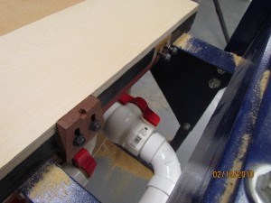
The new pneumatic cylinders are mounted to an extension that I added to the base layer of the table. The aluminum pistons pop up or down at the touch of a button and are extremely solid.
So that takes care of part placement on the table. With the other issue of machine calibration I also started with something simple, that I could implement quickly, but that turned out to be a little more time-consuming than I could justify as our needs increased. You might ask, “why not just use the proximity switches that came with the ShopBot?”. My understanding is that the switches that are currently used are somewhat better than the ones that came with my machine, but my personal experience with my own switches is that I could not rely on them to hold the level of accuracy I needed. Those switches are held on by only a single small bolt, which made them susceptible to rotating slightly if bumped or just due to machine vibration. (I’ve since started taking measures to prevent this when setting up a new machine, such as sanding the paint off the area where the switch will be mounted, and using a little epoxy in addition to the bolt when securing the switch in place.) Also, one of my switches had started to fail, and I replaced it with a home-made version that worked reasonably well, but again could not be relied upon for the repeatable accuracy we require.
My initial method of calibrating the X and Y axes was based on how I was taught to set the hairline on my tablesaw fence – by measuring an actual workpiece after making a cut. In this case I wrote a routine that routed an “L” shaped dado with its shoulder exactly 1” from the edge of the sheet, then paused while I measured the resulting distances with digital calipers, and entered the actual measurements using an INPUT statement. The program would adjust the proximity switch values, re-zero the X and Y axes to the switches, and make another cut to verify that the current set up was accurate. How accurate? For my purposes, I decided that anything within .01” was acceptable. Using this system I was typically able to get to within a few thousandths in each direction without too much trouble. We used this system for several years, relying on the prox switches for general use and full sheet cutting, and using the custom calibration program for flip ops or any other tasks where accuracy is critical. Eventually, however, the custom calibration routine became too cumbersome, as it required an empty corner of a sheet, or a dedicated calibration blank to be placed on the table, and once the corner of the blank was used, a fresh corner would be needed for the next go-round. Also, if the operator did not hold the calipers correctly the measurement would be less than accurate. So a faster, more repeatable, less subjective method was called for.
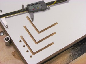
My 1st generation method of calibrating the machine to the workpiece involved milling an “L” shaped dado and measuring the distance from the shoulder to the edge of the sheet. By adjusting the prox switch values and repeating the process, I could get accuracy to within a few thousands of an inch.
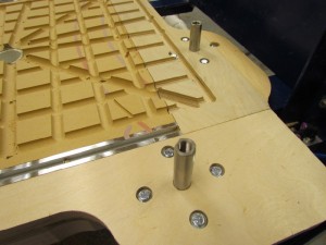
So as part of my recent table re-build, I also incorporated a permanent aluminum XYZ zero block near the 0,0 corner of the table. I used the “Super Zero” block which I purchased from Morris Dovey several years ago, but since I’m not using the fences that came with it, it’s essentially just a small block of aluminum with a hole. It’s bolted into a recess in the table base layer, and wired to the control board with a double nut on the end of the bolt underneath the table. The flat top surface of the block acts as a Z zero plate, and the hole allows the bit to plunge in and zero the X and Y axes to the sides of the hole. This allows us to re-zero any or all axes quickly, regardless of whether or not the table is in use or even completely covered with a workpiece or a full sheet of melamine. To accommodate spiral and compression cutters, which need to plunge fairly deeply into the hole to ensure that the bit will contact the edges of the hole at its circumference, regardless of rotational position, I embedded a short piece of aluminum tube (actually a closet rod cut-off) into the hole.
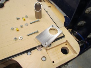
The parts for the new XYZ Zero block are ready to be installed into a recess in the base layer. After being bolted down, the top face of the aluminum block was surfaced flush with the table using an aluminum cutting end mill.
Now we can initiate an automatic re-calibration of all three axes at any time, and have the confidence of knowing the cutter is accurately located in reference to the pneumatic stops, and therefor to the edges of the workpiece. Our accuracy has increased and setup times and re-work decreased tremendously. My only regret is not doing it a long time ago. Check out these YouTube videos to see the new stops and XYZ Zero Block in action.
Leave a Reply