I have been fortunate to visit a good number of ShopBot equipped shops. This has enabled me to compare many setups and implement my favorite “borrowed” ideas into my own setup. Even though I have seen many ingenious vacuum distribution and valve setups I never really saw one that seemed simple. Our previous system had four 240V vac motors bolted to the bottom of the table. Simple.
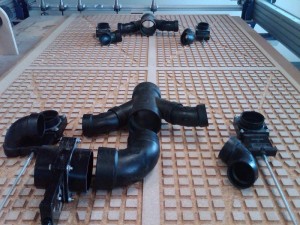
Parts on Table Less Pipe
In order to be able to implement a large blower in the future, it was obvious that a valved distribution manifold was in order, even though a less costly vac source would be used short term. My primary objections to the manifolds I have seen are 1) PVC ball valves are hard to operate and seem to get harder with extended use and 2) the plumbing and fittings required to make these valves accessable add to the cost, complexity and restriction of the system. We now have our design criteria for the manifold system, no PVC ball valves and Keep It Simple, Stupid!
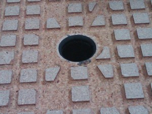
Thru Pipe Glued in and Rounded Over
I decided to use 2” knife valves instead of ball valves. Advantages of these valves are: 1) they are equipped with O-ring seals, 2) seals are replaceable, 3) the actuator handles can be extended to allow remote valve placement with up front control. The only disadvantage is that they cost a few bucks more.
Our plenum was designed as a 49 by 97, 4 zone, very typical to many I have seen. We cut the vac holes thru the table with the ShopBot so that a piece of pipe would glue in directly, eliminating flanges or fittings at that location. We used Corian adhesive for this connection. After the adhesive cured the top of the pipe and plenum were radiused using a 3/8” roundover bit.
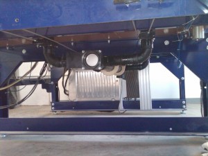
Under Table View Showing Valves, Rods and Dump Valve
The manifold was constructed using 2 double outlet wyes and 45’s for the branches and a 3” main trunk. A 3” knife valve was installed to allow a quick dump of vacuum for both rapid part changes or emergencies. We plan to add an air cylinder controlled by the software for this valve in the future. The 4 zone valves are installed directly under the vac holes just low enough to allow the extended control rods to pass under the table supports. These extensions were fabricated from ¼” aluminum rods and fastened to the valve using bolt couplers. Holes were drilled thru the 2 center leg supports to allow the rods to pass thru. Holes were also drilled into the table support on the –X end for valve handle placement. After all extension rods were in place, they were marked, removed and had threads cut for the handles. Handles were installed with lock nuts.
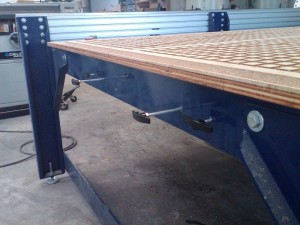
End View Showing 2 zones Open and 2 Closed
This system allows a relatively inexpensive and inobtrusive solution for vacuum distribution. Valves are very easy to operate and even when open do not get in the way. Possible one of the nicest features is that under table access is not hampered. We, like most small shop Owners, need every inch of space we can get.
Less than 5 feet of 3″ pipe and under 4 feet of 2″was required for the complete manifold. The 3″ dump valve would only be needed for larger regen pumps that have a long “wind down”.
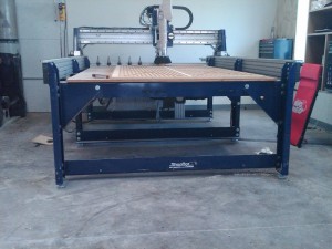
The final picture shows a front view of the machine with the vac manifold installed. You have to look carefully to see the handles, let alone any of the manifold piping.
Leave a Reply