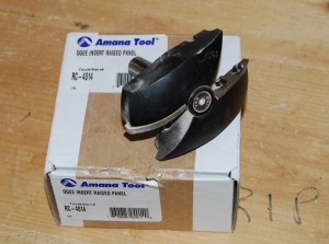
Our quest began when our bit supplier mentioned a bit that would allow us to cut the coves for raised panels. We build 5 piece solid wood doors; until now the panels have been sized with a cross-cut saw and shaped by means of a Grizzly G7214z 7.5 horsepower spindle shaper. Then the panels are installed by hand into the frames. This is a laborious and detailed process as the shaper’s bit, fences, and feeder motor had to be reset from shaping molding every time we needed to make doors. As a result, the prospect of using our ShopBot-Alpha to cut and shape the doors was very appealing.
Doors and Frames
We knew we wanted a process where one person could take sanded blanks, size them and shape them. It would also be nice if he could get the next door ready to be processed while the machine was shaping another door.
This raised lots of questions. What kind of programs would we need to size and shape the doors? Should they be written in the office and then run or should there be user input allowing the operator to tell the machine what size doors we need to make? How would we keep the door panels from flying off the table while a 3.5” bit is scraping 3/8” of solid wood off of a 10” x 20” panel at 11,000 rpm? How could we keep the doors held down so they would come off the table with a constant depth of cut? The answers to each of these questions raised questions of their own.
Where to start?
We began by taking caliper measurements of door panels made from the main species of wood we use to see how thick the panels needed to be to fit into the grove in the styles and rails. These measurements were then averaged and that gave us our final depth of cut. In order to ensure an even finish and keep the stress on the machine and bit low, we decided that they should be shaped in three passes. The first two passes removed most of the material (about 1/8” each) while the last cut took off 1/16” to get a smooth and even finish.
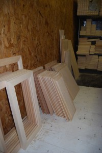
We also had to determine the stage in the process to shape the panels to their final size. Could we do that after they were shaped, could it be done while they were mounted on the shaping jig, or did all that have to be done before? Because solid wood tends to vary in size from what you order and we needed a good sharp corner so the shaping process would come out right, we chose to size the panels first. Thus our building process would go as follows: glue up and plane blanks, size panels, and shape them.
Blanks Being Glued-up
With the depth of cut figured out the question became how do we hold these panels in place while the CNC makes its passes. Because a ¼” bit cutting in three passes does not put a tremendous amount of pressure on the blanks we figured that we could simply vacuum them down to the machine bed with little change of their being thrown off the table. That still left the question of how to hold the panels in place while they are being shaped.
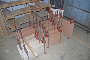
We batted around a few ideas and finally planned to build a two part jig that would vacuum to the table and then have an insert that screwed to the bottom of the panel. We also looked at our most common sizes to determine what size the jig needed to be and how many doors we could process at a time. A jig with three shaping bays seemed to give us the versatility to process most of our standard widths and heights, which we decided to augment with a jig to make full-length doors and other doors for our larger cases.
We used ShopBot’s Part Wizard 2 to design the jigs and inserts that the panels would be screwed to, and then set to work on programming.
Parametric Growing Pains
My experience as a programmer is fairly limited. I have only worked with Visual Basic before and that mostly for Excel data manipulation and calculation. Yet ShopBot’s control language is straightforward and versatile, so I was able to pick it fairly quickly. We knew that we wanted the operator to input the size of the panel and to have the program account for the rest. Writing the sizing program was not too difficult. I used 2 input boxes so the user could input the panel’s width and height, then had the machine offset 3/8th” so the sized blank would be nice and square.
The challenge came in getting the shaping program to work right, which, due mostly to my inexperience, proved to be a painstaking process. It is possible to have the ShopBot move to the corner of the door panel and then reset the base coordinates so that you can use absolute coordinate references. This did not seem to work quite right and nearly ran the router carriage off the table when we tried a dry run. So I used relative values to get the machine to move around the panel. But this was complicated by having to get the machine to the right place before it could start cutting the panels. Furthermore, the bit is made for shaping not plunging. Thus, it needed to move onto the panel at the height it needed to cut. All of this was solved by starting absolute references to get the machine in position and then using the set relative command to process the door panel. We accounted the nature of the bit by moving the router off the corner of the panel, setting the Z value for the height of the cut and then moving on to the corner of the panel to begin shaping.
NOTE: See our upcoming post for part II and final design. If you have questions about what we did or how we did it, please feel free to contact us at (919) 682-6123 or vostro420@verizon.net.
How do I access the follow-up articles to “Making the Perfect Door, Part I”?