Although ShopBot doesn’t officially sell or support Alibre Design software, we’ve used it in-house for many years. All ShopBots are modeled and designed in Alibre and we are big fans of Alibre specifically and parametric design software in general. So when Kirk and Connie Kelsey, woodworkers, designers, and Alibre experts, suggested a web column on using Alibre with a ShopBot, we thought it was a great idea. The Kelseys are longtime contributors to the ShopBot forum and consultants to many ShopBotters, helping them to finetune their manufacturing processes and develop new products. They will be using the same step-by-step approach in this column to show us all how to use the power of parametric design to become more efficient ShopBotters. Even though the full Alibre version is very reasonably priced, the release of the free Alibre Xpress version makes it possible for ShopBotters to try out parametric programming and see if it’s a good fit.
The simplest use of any design program is to create a single part and produce output (such as a DXF file) to allow production of that part. This article will cut right to the main interest of any CNC owner, how to create output from your design so that you can get to manufacturing. Alibre drawing files for this article are available here
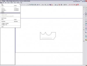
Create your Part:
We will skip over most of the details on how to draw up your part, and leave the details on the use of the Part drawing tools for further articles. In a nutshell ( from the tutorials under CD1):
- Create a new Part file using the icons in the Alibre Home window.
- Create a new Sketch on the default XY Plane using Activate 2D Sketch (upper right).
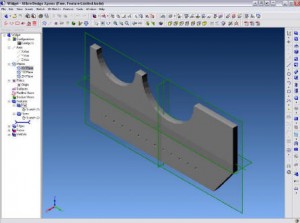
* Orient the “grain” horizontally and attempt to center the part about the origin.
* Add Constraints before Dimensions helps retain the shape of your initial Sketch - Extrude Boss the Sketch to create a solid using the MidPlane dialog option.
Save your new Part, or download the example Part.
Create a Full Size 1:1 Drawing of your Part:
Creating a Drawing at 1:1 scale will allow Export of a 2D DXF file, from which you can create your toolpaths using PartWorks or other software:
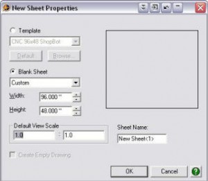
1. File > New > Drawing using a Blank Sheet with drop down setting of Custom. Input a Width of 96″ and a Height of 48″ (or other size to suit your part). The size of the sheet defined is not relevant, although it should be larger than the dimensions of the Part. Make sure the Default View Scale is 1.0 : 1.0, or you will need to change the scale after inserting your part. Press the OK button.
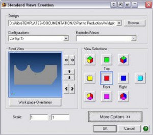
2. If your Part file is open, the Design box in the Standard View Creation dialog will be populated with your part file. If multiple files are open you will need to use the drop down under the Design area to select your desired Part. If you have saved your Part file and closed it, then you can use the Browse… button to locate and select your Part file.
3. In the View Selections area, click on the Top and Right view buttons to unselect them and leave only the Front View selected. If you created your Part on the default XY plane as suggested, the Face of your part should be visible in the Front View graphic window to the left of the View Selections. The buttons around the graphic allow for different orientations should you create your parts in another orientation.
4. Make sure the Scale is again set to 1:1 in the Standard Views Creation window and press the OK button.
5. A light yellow outline will appear in your new Drawing window to indicate the location of your part on the material. Just left click at the default center location where your Part appears, as it does not matter where your part is located on the Material. PartWorks and most CNC programs will compensate for the part location and it does not need to be located in the actual area where you want it cut out of the material.
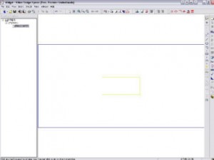
If you have a CNC program that requires the Part in the lower left corner, then you will need to use a 2D CAD or your CNC program to shift the location of the part in the DXF file after it has been created. Although, you can drag the part near the lower left corner as defined by the blue sheet outline to get close enough for practical purposes. The blue outline showing the material boundaries is not included in the exported 2D DXF file. If you failed to provide the correct 1:1 scale, hover near the part until a red view outline appears and Right Click with the mouse. Select Scale from the pop-up menu and set it to 1:1.
6. Save your Alibre Drawing for possible future use. If you change the dimensions of your Part file, you can open this drawing again and it will updated to match your Part file. You can then Export a new DXF file with the new dimensions and other changes made to your Part file.
Export the Drawing to DXF format:
File > Export… to open the Export File dialog box and browse to where you would like to create your new 2D DXF file. Enter a new filename if the default filename is not adequate. Use the “Save as type” drop down to select an export format. We generally use AutoCAD 14 DXF as our output format because it seems to work best with a broad range of software. Experiment with you software and determine for yourself the best DXF format to use. You can even Export an AutoCAD DWG format file if that will work better with you. We normally only use the DWG format for dimensioned drawings when a customer insist on AutoCAD compatible output.
Conclusion:
You may be thinking that it would be better if you could simply output a 3D DXF file directly from the Alibre Part file. Well you can by purchasing an add-on program or by going through SketchUp and exporting to DXF using SketchUp Pro. However, by creating a Layered 2D DXF using this same Alibre Drawing, you can get into production faster by having toolpathed your part in Alibre. Your toolpathing is also associative to changes in the model, and you will not have to start the toolpathing process all over again when you make changes to your model.
Additionally, you can use the same Drawing and Model to create similar parts with different dimensions and the Alibre Drawing toolpathing will updated to match changes to the model. By creating named layers, you can simply match up a pre-defined tool within PartWorks (or other software) with all geometry on that named layer. Look for the article on creating Layered DXF output.
If you are using PartWorks, you should select the geometry after you import the DXF file and use Join Vectors to eliminate any gaps between your geometry. Even though everything is constrained properly in Alibre, PartWorks does not recognize the closed nature of all geometry exported from Alibre. But, it is a simple matter to Join Vectors on the imported DXF file.
Now that you know how easy it is to create DXF output and quickly get to cutting parts, you can relax and learn to use the Alibre Part 2D sketching tools and other techniques to create more complicated Part designs.