OK, as promised I’d like to explain how I use the ShopBot and VCarve Pro/Partworks, along with my favorite CAD program, to nest and cutout parts from full sheets of material, including working with the RTA (Ready-to-Assemble) fittings that you are probably familiar with. Some people have a less-than-favorable impression of those sometimes-annoying little studs and cams that are used extensively in the “flat packed” furniture that you can get from places like IKEA and Office Depot, since like many innovations they often caused as many problems as they solved when first introduced. And yes, they tend to be used mostly for inexpensive (OK, cheap) items made out of particleboard that sometimes (OK, often) feel, well, cheap. But the truth is that modern RTA fittings are well-engineered and very effective for allowing you to machine parts that can be assembled fairly easily by almost anyone with a screwdriver and a hammer, either in the shop or on the job site. So far I am using them for all my closet parts, which they are perfect for. I’m not using them for my cabinets (yet) with a few exceptions – but I plan to use them for my own kitchen cabinets so you can take that as a pretty good endorsement if you like. And if you have no interest in using them, well, hopefully there will still be an idea or two in this column that will make it worth reading.
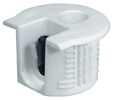
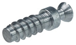
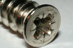
A sample Rafix cam and stud. The cam requires a 20mm hole and the stud screws into a 5mm hole.
So in this installment I’ll start by describing the fittings I use and how to draw them on the parts to be machined, talk briefly about nesting the drawn parts onto sheets, and finish up with my process for creating toolpaths from those nested sheets. The fittings I use are called Rafix, and I get them from Hafele, a major supplier to the furniture and woodworking industries. (You can get similar products from many other sources as well.) There are quite a few variations of RTA fittings, some of which require holes to be drilled into the edges of the material to be joined, which is a task not particularly well-suited for the ShopBot. One of the reasons I like the Rafix fittings is that all the machining is done to the face of the panel, allowing me to machine for the fittings and cut the parts out of the sheet in a single operation. The Rafix system consists of two parts, a metal stud that screws into a 5mm diameter hole and a plastic insert with an integral metal cam that presses into a 20mm diameter hole. The 20mm hole is positioned slightly overlapping the edge of the part, allowing the cam to mate in a simple butt-joint with the metal stud. Specifically, the 20mm hole is placed with its center 9.5mm from the edge of the part, and the stud is placed where it will fall centered in the edge of the part with which it mates (based on ¾” thick material). So when laying out the parts I simply draw a 20mm diameter circle in the proper position on the appropriate part, and a 5mm diameter circle on the mating part. With my toolpathing system I could actually draw circles of any diameter on the part as long as the center of each hole is in the right place, but it’s easier to visualize the finished product with the holes drawn accurately sized. I typically use two fittings per joint for parts up to 16” wide, with extra fittings if needed for wider parts. I usually place the fittings 2” in from each corner, but I go a little closer to the corners for parts narrower than 12”.
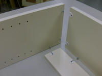
Typical fittings located for a corner joint. The metal studs screw into 5mm holes using a Phillips or #1 square drive bit. The first few can be a little awkward since they are small and the metal is soft, but after a while you can do it with your eyes closed. The cam fittings get knocked into the 20mm holes with a hammer or mallet. They need to be reasonably well oriented with the hole – the flat edge should match up with the edge of the part – but there is some leeway so they do not need to be perfectly aligned.
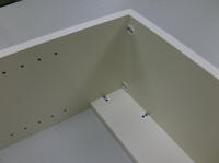
The assembled joint. The cams are secured to the studs with a turn of the screwdriver and are oriented so that the screwdriver is held at a slight angle to allow clearance for your knuckles. You can use a regular #2 Phillips driver, but a “Posi-drive” screwdriver (which is a special type of Phillips screwdriver) works best if you will be doing a lot of these.
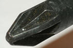
You can tell a Posi-drive screw and driver by the little grooves between the slots in the screw head and the extra little ridges between the four standard ridges of the screwdriver tip. They allow a more positive connection between the screw and driver, which means more torque with less slipping.
If you are not using stand-alone CAD (Computer-Aided Design) software you can draw the parts and the circles for the fittings directly in VCarve (or Partworks). Since I was already proficient in a separate CAD program (I use DesignCad, but any CAD program should be capable of doing the same thing) I still find it easier to do most of my drawings and nesting in DesignCad and then import the nested sheets into VCarve. (I am using VCarve Pro 4.6, but if you are using PartWorks just substitute PartWorks for VCarve Pro for the rest of this article – they work exactly the same way).
Once all the parts are drawn, they have to be arranged (nested) on the sheets from which they will be cut. This is a simple matter of drawing a rectangle to represent the size and shape of the material, usually 48” x 96” or 49” x 97”, and then placing each part on that rectangle. The challenge is to arrange the parts to minimize waste, a process that can be tedious and time consuming when there are a lot of parts of varying sizes. I’ve gotten pretty good at maximizing the yield, at least for the closet parts where there are a lot of repetitive sizes. Some jobs just fit better on the sheets than others. Once the parts are drawn and nested I export the sheets and bring each one into VCarve for toolpathing.
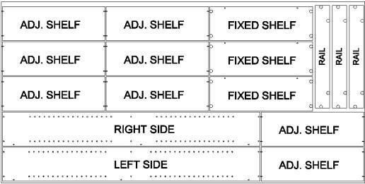
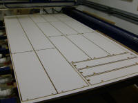
Here’s a sample sheet layout for a small shelf unit with two sides, three fixed shelves (top, bottom, and middle shelf), three rails (one for each fixed shelf) and eight adjustable shelves. The parts are sized so the entire unit can be cut out of a single sheet of plywood or melamine. The little U-shaped vectors on the adjustable shelves will be cut ¼” deep. The resulting recesses fit over the adjustable shelf supports, to keep the shelves from sliding out of position. [Download sample file]
OK, so let’s take each layer and work out the nitty-gritty details. I use layer 1 for the part outlines. As previously detailed I use a roughing pass and a finish pass to cut the parts out. For both passes I use the Profile toolpath with “Outside” selected. For the roughing pass I use a climb cut with an allowance of .02 and a cut depth of .73 (for .75” material). If I’m cutting melamine I set the cutter’s pass depth greater than the material thickness to make the roughing pass in a single cut, but for plywood and MDF I set the pass depth less than the cut depth in order to make the roughing pass in two steps. The finish pass is done with a conventional cut using 0.0 allowance and a cut depth 0.012” greater than the material thickness. For this pass the cutter’s pass depth should be greater than the cut depth so that the finish pass will be cut in a single step. The roughing pass and finish pass toolpaths get saved into a single .sbp file. Even though I mention the part outlines first and use layer 1, the part outlines will be cut last, after all the other machining is complete.
The 2nd layer is for the 20mm holes. For the 20mm holes you could simply use a pocketing toolpath but I wanted a little more control, so I created a small file (RTA Fitting.sbp) which routs one hole just the way I want it. It uses a CC (Cut Circle) command with a spiral plunge to drill a slightly undersized hole, then another CC command at the final size to create the final hole size. It then moves the cutter to the center of the newly machined hole before raising it back up to safe jog height. As outlined in my previous article, I customized a standard VCarve postprocessor so that I can use a Drilling toolpath, but instead of drilling each hole the resulting .sbp file will move the tool to each hole location and run the RTA Fitting.sbp file with a 2D offset.
The sample shelf unit in VCarve/PartWorks. Each layer gets its own toolpath and each toolpath will be saved with its own customized postprocessor (except the outline layer gets two toolpaths and is saved as a single .sbp file). Each resultant .sbp file will be called in order by a master file.
For the 5mm holes (layer 3) I use an auxiliary air drill and another modified postprocessor which drills the holes using the appropriate variables to define the offsets in X and Y between the drill bit and the router bit. If you don’t have an auxiliary drill you can just use a standard Drilling toolpath.
My 4th layer may not apply to many people but for my closet client I have to put notches in the adjustable shelf ends. The notches fit over the shelf supports to prevent the shelves from sliding out of the cabinet. For this I use a Profile toolpath with “On” selected so the bit will follow the vector. I rout the notches ¼” deep in order to ensure a clean top surface since I’m using a compression cutter. Anything less than ¼” deep will lead to chipping of the top surface.
The sheet of parts, ready for edgebanding.
Since I’m using customized postprocessors to output the .sbp files, I have to save each layer as a separate file. So I now have four files for each sheet that I plan to cut. I could just run each file in the appropriate order, but since I usually have a lot of sheets to cut I use a master file which calls the 5mm holes, 20mm holes, adjustable shelf notches and outline files in order for each sheet, with appropriate speed controls, pauses between sheets, and spindle and dust collector switching. My current master file works but I have several improvements in mind so it’s still a work in progress. Hmmm, sounds like an idea for a future column.
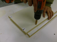
The fixed bottom shelf really should have the cams on the underside, to prevent the shelf from falling away from the cams (especially if the unit will be mounted to the wall, as many closet installations are). That means that the 5mm holes for the shelf-to-rail connection need to be on the opposite face from the 20mm holes. Instead of putting the already cut part back on the ShopBot to drill the 5mm holes in the other side, I find it easier to drill both sets of holes normally during the initial machining, then drill the 5mm holes through the part by hand. The resulting unused holes on the underside won’t be seen once the unit is installed. In the picture notice the short piece of dowel over the drill bit to limit the drilling depth, and the piece of scrap material under the workpiece to prevent blowout.
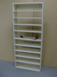
The completed shelf unit. The RTA fittings are surprisingly strong.