If you’re like me you’ve come across situations where you’ve had something that you wanted to cut…maybe something like a piece of molding or a boat rudder…that had the same cross-section along its length. This happened to me recently when a contractor brought me a piece of door corner trim from an old house that he was working on and needed 6 copies made of it.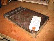 Robert had rejected a couple of options before he came to see me. He had thought about ordering custom shaper blades but that would have been expensive and taken a couple of weeks. He could have hand-ground his own blades but that would have involved ordering blade blanks, waiting for them, and then spending a half day (at least) of some pretty tedious work trying to get them the correct shape while keeping them balanced. For the small number of copies that he needed, CNC cutting seemed like his best solution.
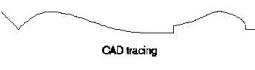
When he brought the original to the shop we worked through a couple of options for duplicating them. Probing the whole piece would have been simple but really would have been overkill…we would have ended up spending a whole lot of time getting points for a shape that really doesn’t change much. What we really needed to do was to create the Profile…a cross section of the shape…and then extrude it along a straight line. It seemed like a handy utility to have so after a little programming work the Extruder was born.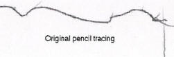 To use the Extruder you first need to create a 2d Part Wizard toolpath file of the profile and then the Extruder “flips” the profile on edge and extrudes that profile along the specified length. There are a couple of different ways to create your original profile drawing, but the quickest way for this job was to just stand the piece on edge on a piece of paper and trace the edge with a pencil. A quick scan of that tracing on a flatbed scanner created a bitmap file that we then manually traced in TurboCAD with curves and straight lines. Once the tracing was as close to the original as we needed it to be we discarded the bitmap from the CAD drawing and saved the file as a dxf file so that we could import it into Part Wizard.
This certainly isn’t the only way to do it, though…there are lots of ways to generate your original profile. Some shapes are easier to draw directly in CAD, like airfoil shapes that are specified by formulas for their cross-sections. You could also use a probe with one of the 3d dxf options to do a pass or 2 across the pattern and then import that into a CAD program. It doesn’t matter what method you use as long as you end up with a good profile that you can get into Part Wizard.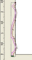 Once you’ve gotten your Profile drawing into Part Wizard it’s time to create a “Profile” toolpath. Although you’ll be using a ball-nose bit to cut the file, you’ll create the profile toolpath in Part Wizard with an end mill of the same diameter…if you’re going to be cutting the extrusion with a 1/2″ ballnose bit then create the toolpath file with a 1/2″ end mill. This may seem funny at first but imagine that the end mill is really a ballnose bit laying on it’s side…the end mill really represents the “ball” at the end of the ballnose bit that will eventually be doing the actual cutting after the “flip”.
I’m not going to go though all the steps for creating your profile toolpath…it’s not all that different than any other toolpath generation…but there are a couple of things that you need to keep in mind
*) You want to make sure that you create the toolpath so that it cuts in ONLY ONE PASS. The easiest way to do this is to set the cutting depth so that it’s smaller than the stepdown setting for the bit you select. Since the Z-axis settings are ignored in the Extruder a very small cut depth like 0.001 or so should be fine.
*) Think about the direction that your extrusion is going to be done before you create your toolpath. If you’re going to be extruding your profile parallel to the X axis then you’ll need to arrange the profile so that it will be “flipped” around the Y-axis, and the same is true when you’re extruding in the Y Axis. Clicking the “?” buttons will help you figure out which one you want.
*) Once you’ve created your toolpath the final step is to save it using either the plain “inch” or “mm” post processors, NOT with any of the “arc” ones.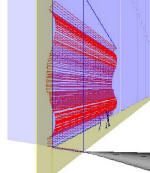 Creating your toolpath is really the hardest part…after that it’s simple. Start the Extruder and select the axis that you’re going to extrude along. Then select the start and end points of the extrusion…this determines the length of the extrusion. The SafeZ setting is how high you want the bit to be above the highest point of the “flipped” profile which is calculated when the flip is done.
The “maximum segment length” setting ONLY breaks up long straight sections to increase resolution. It doesn’t decrease the resolution if your segments are closer together than that…if the segments in your profile are too close together you’ll need to redo your profile with a larger tolerance.
When you’re done just click the button and you’ll be asked to select the file that you want to extrude. The virtual “flip” will be done and the extruded file will be saved with the original file name with “_extruded.sbp” added to it.
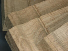
The finished trim pieces
Note: We didn’t need to use this feature on the trim pieces but you’re also given a choice of tapering the extrusion in height, width…perpendicular to the extrusion direction, or both. All tapering is done toward the axis that the extrusion is parallel to, so if the profile is “centered” on that Axis, with half of it above and half below, then the extrusion will taper toward the middle. If the whole profile is above the axis in an X-axis parallel extrusion then it will taper “down”, etc. Play with it a little in preview mode and it will be pretty obvious what’s happening.
As I said in the beginning the Extruder can be used for a lot of other uses besides molding. Shaping rudders and wings is a natural use for it and it would be great for one-off curvy furniture and architectural pieces.
Installing the Extruder
The Extruder comes packaged in a zip file and there’s really no installation involved…the ShopBot control software has already installed everything it needs to run. Just unzip it to a convenient place like your desktop and when you’ve created the 2d profile that you want to extrude just click the Extruder icon. It’s as simple as that. As a bonus the download includes the “Flipper”, a program that takes the same kind of 2d Part Wizard file and just does the “flip” that converts X or Y axis values to Z-axis values, without doing the final extrusion step. Finally there’s also a folder with sample toolpath files for you to play with, just to help you get the hang of things. The Extruder and Flipper are constantly being updated with new features and fixes so to make sure that you have the most recent version we have the most recent Extruder available in [ShopBot Labs]
I hope the Extruder and Flipper are helpful to you. The next Bill’s Corner project will be another program that I think you’ll find…well…interesting.