Cutting a Nerdy Derby Flat Track
Design Decisions:
The Nerdy Derby Flat Track project was created with three criteria:
- It had to be shape-compatible with the original Nerdy Derby track, so that the same cars would fit on each track
- All the parts had to be cut-able with a Handibot, so no part could be larger than 6” x 8”
- It needed to be material agnostic, so that a set of parts could be cut out of whatever material was available. This allows them to be fabricated from waste material as described in Distributed Manufacturing as Waste Management
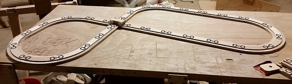
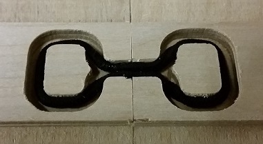
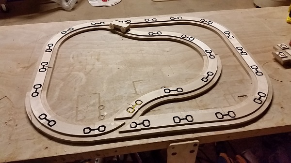
This Flat Track design has evolved through many versions, but two have bubbled to the top. My favorite one I just call “Flat Track” and uses rubber bands, ORings, or hair ties to make a flexible, “fluid” connection.
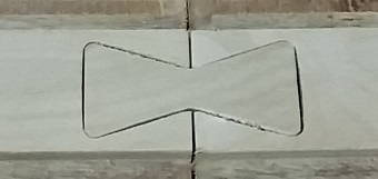
The other version uses bowtie-shaped connectors that fit into cutouts in the tracks. It works just fine but has lots of little fiddly bits to keep track of.
Files for both versions are included in the Project Download so that you can make up your own mind which one to make.
Materials and Bits:
Downloading the Project Files (link) will get you several folders and files. If you just want to cut track parts without fiddling with design files, the ShopBot Part Files have already been created for both nominal 1/2″ material that’s really 0.47″ thick, and nominal 3/4″ thick material that’s actually 0.73″ thick. They have been toolpathed for a 1/4″ bit that’s zeroed to the top of the material, and have speed settings for cutting with a Handibot. The files cut through the material an extra 0.015″ deep, with two tabs holding each part (More about this later)
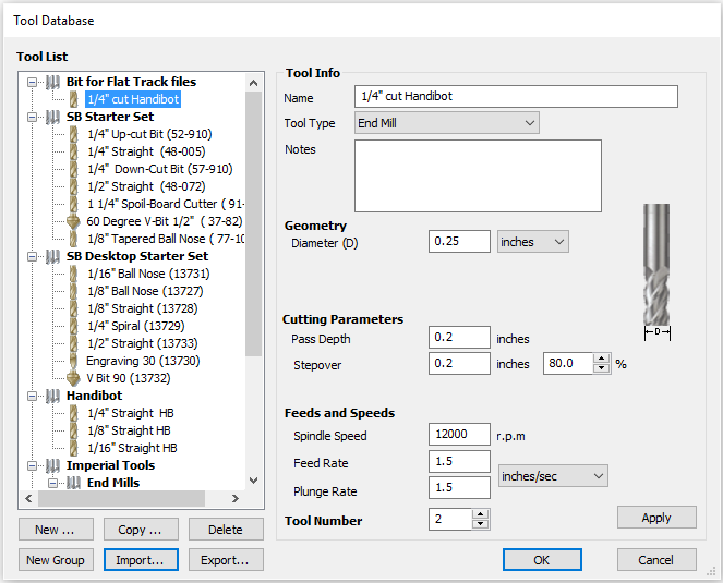
The Project Files also include the tool database setting for the bit I used to toolpath those ShopBot files. It’s named “Bits for Flat Track files.tool”, is in the Shared VCarve Files folder, and if you use the IMPORT function in the VCarvePro tool database,a new tool group with this new bit will be created.
There’s a great video about working with the Tool Database on the Vectric website
Cutting Files:
If your material thickness is different than those two sizes, or you’re just feeling adventuresome, the VCarvePro files for each part are included in the project files.
The VCarvePro files uses an interesting feature called “Document Variables” that make it easier to modify the toolpaths. In our case, they are used instead of inputting a number in the Cutting Depth field when setting up toolpaths, but can be used just about anywhere in the toolpath. You can find the list of Document Variables at the bottom of the EDIT menu in VCarvePro, and opening it will show the three variables that I use.
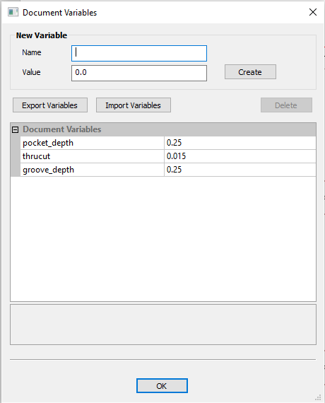
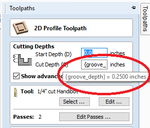
The “groove_depth” variable is the depth that the groove is cut that holds the elastic connectors in the “Flat Track” files. It’s not used in the bow-tie versions. “pocket_depth” is the depth of the pockets that are machined to make the lower sections in the track that the car wheels ride on. The default value of 0.25″ matches the regular Nerdy Derby track, but since you’re creating your own set you can do what you want!
If you open the Groove or Pocket toolpaths and look in the Cut Depth field, you’ll see text where you usually see numbers. If you hover your mouse cursor over that textbox you can see its value.
Calculating with Variables:
The third Document Variable is “thrucut”, and is used a little differently. The Document Variables are defined by the creator of the file, but there are several Special Calculation Characters that VCarvePro also understands.

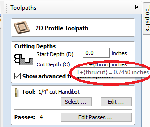
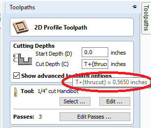
The one we use is “T” which represents the thickness of the material as defined in the Job Setup form. Adding the value of our “thrucut” variable to the thickness value lets us cut a little bit deeper than the thickness of our material to make sure that the parts are cut all the way out.
We define that total cutting depth in the “cutout” toolpath cutting depth field by typing “T”, then “+”, and then hovering with our mouse until a list of all of our Document variables appears. Select “thrucut” from the list and your new formula appears in the box. Hovering your cursor over it shows its current value based on our default material thickness of 0.73”.
This may seem like an overly complicated way to set cut depths, and for simple parts like these it may be. It is a BIT more complicated than just typing in a number, but what happens if your material thickness changes? You need to find all the places that cut all the way through and change the cutting depth in each toolpath. Or if you want to it cut a little deeper (or not as deep) you’ll need to modify each toolpath!
Let’s say the material we have is really .55” thick. All we have to do is to open the Job Setup in the EDIT menu and change the current value of 0.73” to your new value: 0.55”
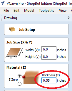
To see this change you just need to recalculate the toolpaths, and anywhere you use the “T” value will be recalculated and will have the new cutting depth.
The Document Variables file that I used, “Nerdy Derby Flat Track.DocVars”, is include in the Shared VCarve Files folder. Don’t be afraid to play with these settings … you can always import this file from the Document Variables form to reset them if you get them messed up.
Using Merged Toolpaths:
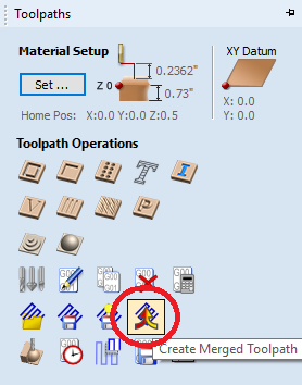
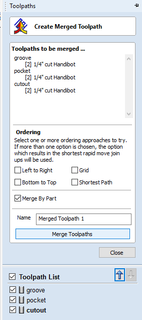
The last fancy feature is only used in the files for the straight sections, because they have multiple toolpaths—grooves, pockets, and cutout—in multiple parts. If we had just selected the three toolpaths and generated a part file from them, it would have cut them in their order in the list. It would have worked fine, but wouldn’t have been particularly efficient. It would have cut the groove in both parts, then cut the pockets in both, and then cutout both. Lots of moving back and forth.
What we actually want to happen is to have the file finish cutting ALL the features in the first part before moving to the second. That’s what a merged toolpath does—combine the features in each part to make the cutting more efficient.
One thing to be aware of is that merged toolpaths are NOT re-calculated when the toolpaths that they were built from have been modified. Don’t worry that you’ll forget though, because you’ll get lots of warnings after you’ve recalculated a toolpath that was used in a merged toolpath. You just need to delete the merged toolpath and generate a new one, that’s all there is to it!
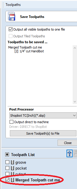
Also remember that since the new merged toolpath was built from the other toolpaths, when you save your part file you ONLY use the merged file. I’ve renamed the merged toolpaths in the VCarvePro file to hopefully help you remember!
Want to learn more about using Merged Toolpaths? Watch this Vectric Video
The project files can be downloaded from Handibot Projects in a zip file. To help with prototyping and figuring out how many pieces of each you need, Sketchup files are available in the 3DWarehouse to build your own virtual track layout.
Enjoy your Flat Track and feel free to modify the files to fit your needs,
Bill
NOTE: These files are licensed under the Creative Commons Attribution 4.0 International License.
You are free to:
Share — copy and redistribute the material in any medium or format
Adapt — remix, transform, and build upon the material
for any purpose, even commercially.
To view a copy of this license, visit http://creativecommons.org/licenses/by/4.0/ or send a letter to Creative Commons, PO Box 1866, Mountain View, CA 94042, USA.