One of the things that we always had in mind for our ShopBot was to use its automation capabilities to replace some of the operations that we had previously outsourced. Due to increasing lead times and decreasing quality, our first chore was to start in house manufacturing of the solid Maple Dovetail Drawers we use in our cabinetry. After dusting off our Porter Cable dovetail jig and making a few test cuts, it became perfectly clear that we needed another method. The chatter and inconsistent fits were as bad, if not worse, than the ones we had received from our supplier. I used the general idea of the hold down and cutting methods from the tried and true PC jig as a guideline for my jig and toolpath geometry. If you are looking for a way to cut half blind dovetail drawers on your ShopBot, this article should get you pointed in the right direction. Other than a few “investment grade” wood scraps, the only purchase requirement is a ½” diameter 14 degree dovetail bit. Since holding the drawer sides for cutting is probably more important than the cutting itself, we will start with construction of a jig.
Jig Construction
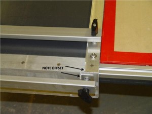
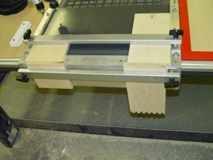
I made my jig from ½” PVC solid sheet and some aluminum extrusions I had at the shop. I dimensioned it so that I could cut a pair of up to 11” wide drawer corners at one time. I also made the fences and front lip from aluminum so that I could use the control software to zero the jig. Others that I have sent the file to have mounted their jig and then cut the fences with the Bot the insure accuracy. I used 8020 T slot extrusion, with T knobs to hold the material to the jig. Your jig needs to be wide enough to cut a pair of corners on the maximum width drawer side that you anticipate. My final width was determined by the T Slot mounted to my table, which allows me to use bolts and T nuts to fasten the jig to the ShopBot Table. You should notice the lineup bracket behind the front clamp bar. This bracket offsets the vertically mounted piece half the center to center distance of the lobes and slots. (More on this later)
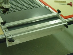
What you make your jig from is not important. What IS important is that it is very square, the fences are exactly parallel, and the front and top are perpendicular. You should also make sure that the fences and brackets are not as high as the thinnest material you plan to cut is thick. 5/8” is the thinnest material we use, so my fences are ½” high. You will also need to be able to cut beyond the end of your table in the –X direction. On my setup, I am cutting between the limit switches and the hard stops, so I must turn the limit checking off to use the jig. You will need to have a very secure mounting method as cutting end grain in dense hardwood puts a lot of stress on both the jig and the tool. You may also want to consider building the jig and cutting the fences parallel with the ShopBot. You will need to know the exact distance between the fences to be able to cut pairs of corners accurately. Holding the material down to the jig is also very important. In order to get my aluminum extrusion to work better, I sanded the contact side and then bent the center towards the jig 1/16” for better contact across the material.
SETTING UP MATERIAL AND USING THE JIG:
The following 2 illustrations show the orientation of the jig on the ShopBot table, the drawer parts and how they fit into the jig, and the orientation of the parts for cutting.
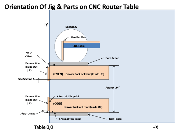
You should notice that the jig should be zeroed as shown by the arrows. These zero lines correspond to the front edge of the jig and the edge of the “odd fence.” The Z zero is the top of the material (shown in section “A” as “Must be Flush” The cutting file also needs the exact distance between the fences. The dimension is shown as 24”, but can be any size. Also note that the top edge of the vertically mounted drawer side must be flush with the top surface of its mating front or back. The 7/16” offset is required to make the top edges of the sides be flush with its mating front or back. If you wish the sides to be lower than the fronts/backs, then increase the offset by that amount. We do this occasionally to allow the use of radiused edge drawer sides. You do not have to cut the mating corners together on the jig. As long as you have proper orientation, you can make all the drawer cuts in 2 operations.
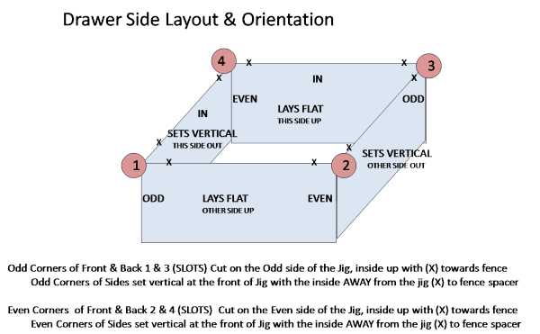
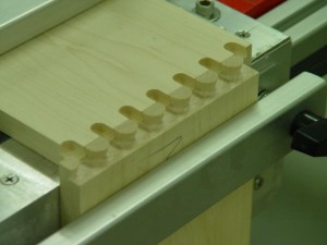
This illustration shows how I setup my drawer parts and mark them for cutting. I pencil “X’s” and corner numbers on all the corners as shown. The “X’s” go on the top edge of the parts to orient them to either the fence or the offset bracket. The corner numbers go on the insides of all pieces, as they will be either up or out when properly oriented in the jig for cutting. It took me a while to learn this marking method, but, once learned, it makes dovetails much easier. The PC dovetail sheet linked to below shows a slightly different method, you may like theirs better.
The cutting lengths for the drawer parts are as follows:
* The Fronts and Backs are cut the same width as the finished drawer width.
* The Sides are cut to the finished length of the drawer less one material thickness. Due to variations in cutting depths, you may have to adjust this length.
We use Blum Tandem drawer slides and our dado for the bottom is ½” from the bottom edge. Other brands may have different requirements. We use ¼” for a dado depth. Care should be taken not to cut the dado so deep that the lobes of the dovetail are cut, as this will show in the finished product.
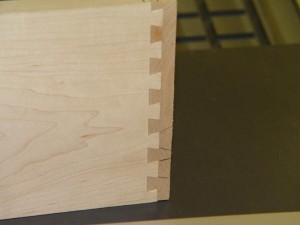
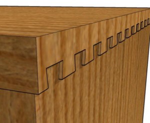
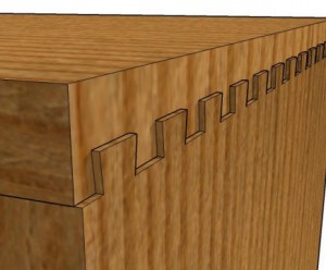
These pictures show test corners before and after cutting
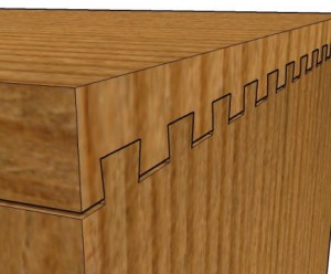
Here is an assembled test corner:
The Cutting File
The ShopBot part file to cuts the dovetails is available from ShopBot Labs. It will give you the option to cut an odd or even numbered single corner, or a pair of corners. When cutting a pair, the pieces must be an odd and even pair properly oriented. As with all untested parts files, you should air cut with it before running with a cutting tool. The file will give you options to cut trial pieces to make your adjustments, select cutting locations, adjust cutting depths and slot lengths, and repeat cutting for same width parts. You will have to edit the parts file to match your jig fences and possibly to match your jig location on your table. You may also have to adjust the cutting speeds to fit your machines cutting abilities. In any event, if you don’t feel comfortable modifying a parts file, this may not be for you.
The file is designed to use Porter Cable #43704 (1/4″ shank) or PC#43750 (1/2″ shank) or equivalent bits. I highly recommend the ½” shank bit. There are many 14 degree ½” diameter dovetail bits that are made by other manufacturers that should work also.
If the fit is too loose adjust the Depth of Cut to be deeper. If too tight, make Depth of Cut shallower
If the side panel is inset, decrease the Slot Length value
If the side panel extend past the other panel, increase the Slot Length value
This jig and cutting file were made to replace the Porter Cable Dovetail Jig jig with a CNC router. Any and all of the cutting operations shown in the manual should be able to be cut using this cutting file, with a few adjustments. By changing the file variables, you will be able to change the cutting depth, the slot width and depth, the pin radius and the distance between pins and slots. With a few different bits, and a little practice, you should be able to cut any joint shown in the manual. You can view or download the complete manual from the Rockler website
Moving forward:
If you study the Porter Cable manual, you will notice that changing the lobe and pin spacing, the slot length (distance the bit travels into the jig slot) and the router bit, are the only changes you will need to make in order to cut any of the dozen or so types of joints shown. All of these adjustments use variables that you can either edit in the parts file, or fill in as inputs.
Whether you are looking to build a single drawer for a unique cabinet, or a couple dozen for the next kitchen coming out of your shop, with a little practice and a few adjustments, you should be able to use this jig and cutting file to make high quality joints. As you use the jig you will find more uses for it. We have also used it for end and edge drilling small parts, cutting slots in the edge of thin plastic and cutting mortise and tenon joints.
Enjoy!
Next Article: We kick the Vacuum up a notch