 |
A few months ago I replaced the worn out plywood and MDF table which came with my ‘bot (the demo model from the 2004 IWF) with a custom-designed 8 zone vacuum table. There has been a lot of interest in vacuum tables recently, and since I posted a few pictures of my newly upgraded setup on the TalkShopBot Forum I’ve received several questions and requests for more info, so I thought I’d share some details. Now that it’s been in service for more than a few jobs I can safely say it works well, however keep in mind I designed this system to suit my particular needs so your mileage may vary. |
I started by laminating a piece of ¾” 4×8 Baltic Birch Plywood with 2 sheets of “brown backer” laminate, which I figured would help minimize changes in moisture content and help stiffen the plywood. It also made the surface non-porous, which would come in handy as the plywood serves as the bottom layer of my vacuum platen, and with the laminate layer on top of the plywood I don’t need to worry about losing vacuum through the bottom of the platen. I then bolted the plywood to the steel cross supports using countersunk holes, but not before carefully checking the limits of travel of the machine so that I was sure both my router and my drill unit would be able to traverse the entire length of a 96” (or 97”) sheet. By moving the gantry all the way to one end and then the other and making note of the tool locations at each extreme I determined there was only about ½” of leeway as to where I could bolt the plywood down and still have full machining capabilities with both tools. The table ended up only about ¼” off center from the cross supports in the X direction. In the Y direction I determined that by centering the table on the cross supports I had the maximum flexibility to reach the edge of the workpiece with the router and would still be able to reach the entire sheet with the air drill, which is offset from the router about an inch in the Y direction.
So now I had the plywood bolted down and in the proper position. I measured the locations of the steel cross supports and drew them in my CAD drawing of the table, to be sure my plumbing holes, T-track and such would not conflict. This allowed me to lay out my vacuum zones, plumbing, and T-track locations. The fun was just beginning.
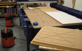 Gluing the MDF platen down in four pieces – |
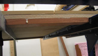
Although I had been planning (and dreaming about) the new table for some time, I hadn’t figured out how to bond the MDF layer that would serve as the vacuum platen to the plywood/laminate sandwich. But I had been scouring the Forum regularly for ideas and sure enough Brady Watson came through with his idea about a one-piece platen/spoilboard. I modified his idea for the next step. After scuff-sanding the brown laminate with a handheld belt-sander, I used the Shopbot to rout holes for my Fein vacuum hoses where the larger holes for the 2” PVC plumbing would eventually go. I then cut the MDF platen into 4 quadrants, and routed a simple grid into one face of each quadrant. By flipping the MDF and placing it over the table with the routed grooves down, I was able to securely glue the platen to the table, one quadrant at a time, using polyurethane glue and the Fein vacs hooked up to 2 holes per quadrant. (If you use polyurethane glue, use it sparingly – just enough to wet the surface. A short piece of baseboard or crown molding makes a great glue spreader.) I followed this with a border of solid hardwood glued and clamped to the underside of the table, all the way around the perimeter. I figured this would add stiffness, make clamping easier (not that I expect to do much clamping with the new vacuum table, but you never know, right?) and make it easier to attach stops securely to the edges of the table. |
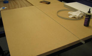 A strip of edgebanding between the platen quarters blocks air from leaking between zones. |
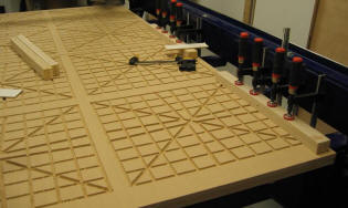 The vacuum grooves are cut and hardwood edging is being glued to the underside of the perimeter. |
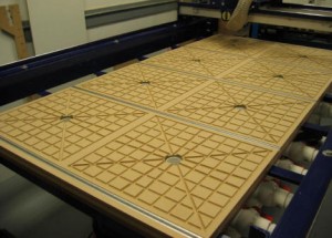
Once the layers were built up, I used the ‘Bot to trim all four edges of the table, being careful about the location of the cross supports. I then surfaced the MDF platen flat, routed the grooves for the T-track and the vacuum grid, and enlarged the holes to fit the 2” PVC. [My PartWizard .art file for the grid and track. To download, right-click this link and save file to your computer.] I secured the T-track using epoxy and screws. I’ve only had a need for the T-track once in 3 months, but I expected it to be one of those things that while only used occasionally makes life much easier when it does get used. It did complicate the design and construction (as well as adding to the cost), so I suppose you could leave it out and still have a mighty nice vacuum table, but knowing the variety of tasks I use my machine for I’m glad I went to the trouble and expense. I have some ideas for hold-downs, which once I get a chance to fabricate them will make the T-track much more valuable to me. A note of caution – the T-track results in my having little or no vacuum on the last couple of inches of table at each end. So far I have not found this to be a major problem, but it is something I have to keep in mind.
 The three layers, ready for trimming. The gap in the MDF will be enlarged and filled with T-track. |
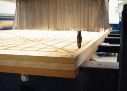 I held my breath while the cutter trimmed the edges, oh so close to the steel cross supports. |
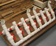
While I was planning and working on the table I was laying out the PVC plumbing and the 16 valves (!) which are the key to my 8-zone system. I do a fair bit of repetitive work on pieces much smaller than 4’ x 8’, so it was important to me to be able to alternate between two zones – while the machine cuts a part, I can be preparing the next part to be machined on the other end of the table. So my system is designed to be used with two vacuum motors, each with a manifold and 8 valves. Fitting and gluing up the pipe and valves was quite an exercise – there are a lot of small parts and fittings, all glued up into one rather large assembly, so it took some planning to figure out what order to assemble the parts in and how to keep everything aligned. The final part of the plumbing system involved connecting the Fein vacs to the manifolds. As it turned out, I had a 2” shopvac hose from a recently retired (read: worn out) old wet-dry vac, which fit perfectly into the Fein outlets and the 2” PVC “T” fittings. A couple of vacuum gauges allow me to monitor the holding power, which is substantial. I finished up with an MDF spoilboard, which I surfaced on both faces to facilitate airflow.
|
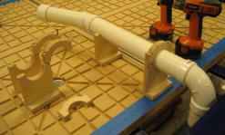 Shop-made pipe hangers for the longer |
 I shimmed the PVC in place, centered in the hole, then sealed it up. |
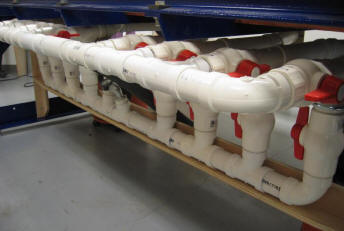 The completed plumbing system. Some day I may add wood handles to make the valves easier to operate. |
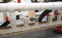 2″ Shop-vac hose connects the motors to the manifolds. Vacuum gauges let me know how much holding power I have to work with. |
So how well does it work? In a word, great! The freedom to place almost any flat workpiece on the table, hit a switch and start cutting is empowering. No more screwing workpieces down and keeping fingers crossed that I put the screws in the right places. No more time wasted creating and running an extra toolpath to locate “safe-screwing” spots. No more clamping the corners of a sheet and running around the machine moving clamps as the parts are cut up. My confidence level increased and set up times decreased substantially. As a bonus, many cuts are cleaner and more chatter-free as the workpieces are securely held at every spot, not just where I put screws or clamps. I can now concentrate on tooling, feed speeds, and cutting strategies instead of worrying about how to hold the workpiece while cutting. Many smaller tasks are now cost effective, whereas previously it would have taken longer to secure the workpiece (and work around the clamps and screws) than it would take to do the task by hand. In short, adding the vacuum table has proven to be one of the most effective upgrades I could have made.
 |
Done. Ready to start cutting! |
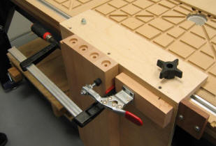 |
I knew the T-track would come in handy sooner or later. |